When upgrading security at a remote utility substation, the decision to integrate modern IP-based CCTV cameras with a new Perimeter Intrusion Detection System often hinges on the underlying network design. Legacy analog systems might have run on dedicated coax cabling, but shifting to Ethernet introduces demands for bandwidth, latency control, and segmentation that can make or break operational reliability. Teams frequently overlook how video streams from dozens of cameras collide with sensor data bursts from PIDS, leading to dropped frames or false negatives during incident response.
In a typical retrofit scenario, such as expanding coverage around a multi-building campus, engineers must balance IT constraints with field realities. IT managers push for convergence onto the corporate LAN to cut costs, while security integrators insist on isolation to prevent cyber risks or multicast storms overwhelming switches. The right approach starts with dedicated VLANs for video and sensor traffic, PoE switches rated for continuous high-power draw, and QoS policies prioritizing alerts over routine feeds. This setup ensures synchronized timestamps via NTP, critical for correlating footage with intrusion events.
Getting this design right from the outset avoids costly rework. For instance, a flat network might suffice for small deployments but scales poorly when PIDS fiber runs converge with CCTV at a central NVR, causing jitter that desynchronizes analytics.

What the design decision looks like in practice
Picture a security integrator tasked with hardening a chemical processing plant's perimeter. The site already has 40 analog CCTV heads on a matrix switcher, and now PIDS microwave sensors need tying into a unified video management system. The network design choice boils down to whether to extend the plant's industrial Ethernet backbone or deploy a parallel security LAN. Extending the backbone risks exposing sensors to operational traffic, while a parallel setup doubles cabling but isolates risks.
In practice, most teams opt for a hybrid: core switches with VLANs trunked over fiber to edge PoE injectors. This allows CCTV streams to multicast within their VLAN, PIDS data to unicast alarms, and both to sync via a stratum-1 NTP server. During a pilot, one integrator found that without proper IGMP snooping, multicast video flooded ports, spiking latency to 200ms—enough to miss correlating a fence vibration with camera motion. The fix involved layer-3 switches at aggregation points, ensuring video doesn't bleed into control systems.
Field teams appreciate designs that support remote firmware updates without truck rolls. For example, grouping cameras by zone on separate SSIDs for wireless bridges reduces interference from PIDS RF, maintaining 99% uptime in rain.
System architecture and integration considerations
At the heart of any CCTV and PIDS network lies a hierarchical topology: access layer for endpoints, distribution for aggregation, and core for VMS integration. Copper Ethernet dominates short runs to cameras, but fiber becomes essential for PIDS spans exceeding 100m, like along fences or pipelines. PoE++ switches handle the 60W draw of PTZ cameras and active sensors, but integrators must calculate power budgets per port to avoid brownouts during pan-tilt operations.

Integration demands careful protocol mapping. CCTV often uses ONVIF for discovery, while PIDS might output Modbus or proprietary serial-over-IP. Gateways at the edge convert these, but network design must account for heartbeat traffic—PIDS polls every 5s can swamp a 1Gbps link if unsegmented. VLAN tagging (802.1Q) keeps video RTP/RTSP separate from sensor SNMP traps, with trunk ports negotiating speeds to avoid duplex mismatches that halt streams.
Scalability enters via redundancy: link aggregation for camera clusters and dual-homed PIDS controllers. In high-assurance sites, SD-WAN overlays provide failover to cellular for remote diagnostics, ensuring alerts reach SOC even if primary fiber is cut.
Operational workflows and field constraints
Daily operations revolve around correlating events: a PIDS alert triggers camera presets, archived via network-attached storage. Network design influences this by enforcing low-latency paths—under 150ms end-to-end—for real-time overlays. Field technicians, often accessing via rugged tablets, rely on VPN tunnels over the security VLAN, but poor QoS lets routine patrols starve forensic pulls.
Constraints like EMI from nearby motors or solar flares on fiber demand shielded Cat6a or single-mode runs. In dusty substations, IP67-rated media converters bridge copper to fiber without introducing failure points. Maintenance workflows include port mirroring for packet captures during false alarms, routed to a dedicated span port to avoid taxing production traffic.
Shift handovers benefit from NTP-synced logs, where a 1s drift turns a midnight intrusion into an ambiguous timestamp match. Designs incorporating IEEE 1588 PTP for microsecond accuracy shine here, though simpler NTP suffices for most retrofits.
Common failure points and design mistakes
One prevalent error is undersizing switch backplanes for multicast video floods. A 48-port Gigabit switch might handle unicast CCTV fine, but 20 H.265 streams at 8MP overwhelm shared buffers without 10G uplinks. Integrators see this manifest as pixelation during motion, eroding trust in PIDS verifications.
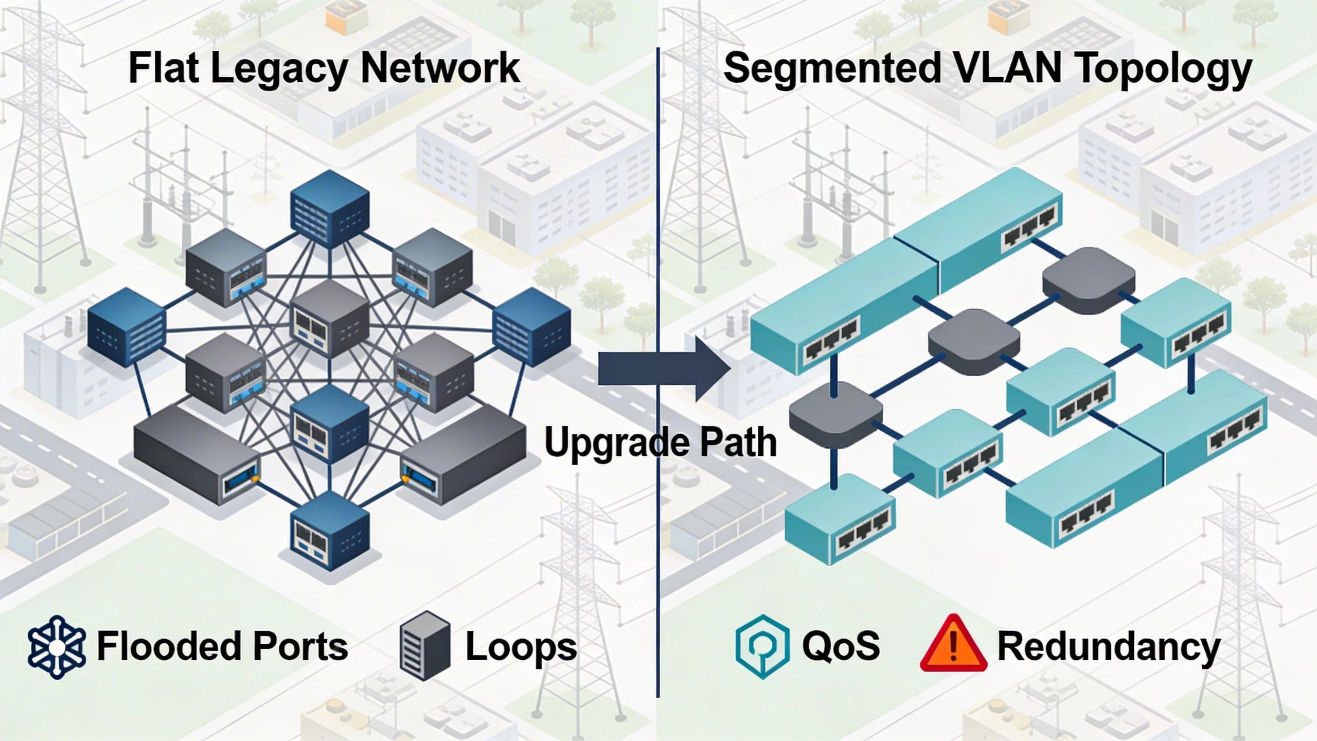
Loop prevention via RSTP is often misconfigured, with default timers causing 30s outages on link flaps from construction. Ignoring cable bend radii on fiber PIDS runs leads to dB loss, dropping signal-to-noise and sensitivity. Cybersecurity oversights, like default SNMP communities, expose sensor configs to lateral movement.
- Failure to enable storm control, allowing broadcasts to blackhole ports.
- Mixing PoE classes without per-port negotiation, browning out heaters in cold climates.
- Neglecting firmware parity across CCTV and switches, breaking ONVIF extensions.
What to verify before procurement
Before signing off on gear, audit switch datasheets for multicast replication capacity and PoE budgets matching your endpoint manifest. Confirm VLAN support extends to wireless APs for PIDS gateways, and test IGMP querier functionality in lab mocks. Procurement teams should demand MTBF figures for industrial temps (-40C to 75C), as rack units fail faster in unconditioned enclosures.
Validate interoperability via vendor playbooks: does the switch honor DSCP marks from PIDS analytics? Check for zero-touch provisioning to speed campus rollouts. Fiber transceivers must match wavelengths for PIDS bi-static links, avoiding bit-error rates that mimic intrusions.
- Simulate peak load: 50% cameras in motion, all PIDS polling.
- Verify failover: pull primary uplink, measure alert latency.
- Scan for vulns: ensure TLS 1.3 on management interfaces.
Where to go next
Explore FortSense 4 for seamless CCTV and PIDS convergence in critical sites. For tailored advice, request a design review. See real-world applications in critical infrastructure security and North America deployments.
Image Production Brief (Internal - Remove Before Publish)
Recommended image count: 3
- Placement: After the introduction
Insert After: Introduction
Purpose: Provides a visual overview of a typical retrofit topology, helping readers grasp the hybrid network layout early.
Prompt: Diagram of a utility substation network: core switch with VLANs trunked over fiber to PoE edge switches, connected to CCTV cameras and PIDS sensors along perimeter fence. Include multicast paths and NTP server. Clean technical illustration, labels for CCTV VLAN, PIDS VLAN, labels in sans-serif font.
Alt Text: Utility site network topology for CCTV and PIDS - Placement: After System architecture and integration considerations
Insert After: System architecture and integration considerations
Purpose: Illustrates wiring details for convergence points, clarifying PoE and fiber handoffs critical to the section.
Prompt: Detailed wiring diagram: PoE switch ports to CCTV PTZ camera and PIDS sensor, fiber trunk to aggregation switch, with gateway for serial-to-IP. Show Cat6a runs, SFP modules, power budgets. Isometric view with color-coded cables.
Alt Text: Wiring schematic for CCTV and PIDS edge devices - Placement: After Common failure points and design mistakes
Insert After: Common failure points and design mistakes
Purpose: Shows before-and-after migration from flat to segmented network, highlighting fixes for pitfalls discussed.
Prompt: Migration diagram: left side flat legacy network with overload icons (flooded ports, loops); right side segmented VLAN topology with QoS, redundancy. Arrows indicating upgrade path, utility campus background.
Alt Text: Network migration from flat to VLAN-segmented for CCTV and PIDS
For isolated security networks, keep the network design separate from one-way export. Use the data diode integration guide to decide when alarms, health, and evidence should leave the trusted side without allowing return traffic.