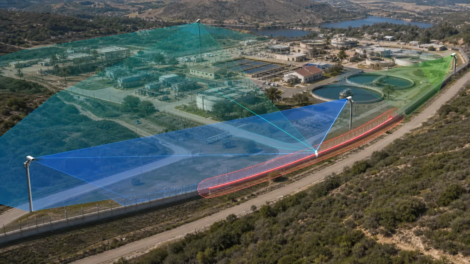
Geospatial alarm-to-camera mapping converts a perimeter event location into a deterministic set of usable verification views. The design should place the alarm on a surveyed route, expand it by the known location uncertainty, intersect that envelope with field-tested camera visibility, and select a primary and fallback view according to availability and operational policy.
Do not map cameras by zone name alone or treat nominal camera range as coverage. The system needs controlled route geometry, coordinate and datum rules, versioned camera visibility polygons, boundary behavior, PTZ preset ownership, degraded fallback, and witnessed field tests.
This is the spatial layer between detection and verification. General operator workflow remains in the perimeter alarm camera-verification guide; localization measurement remains in the fiber PIDS localization-accuracy guide.
Map the Alarm as a Point, Segment, or Zone
A camera-selection engine must know what the source location means. A point alarm identifies a position plus uncertainty. A segment alarm identifies a bounded section of route. A zone alarm may describe an entire fence sector with no finer location. These inputs cannot use the same camera rule blindly.
Point event: buffer the reported location by the validated error envelope and test cameras against the resulting area.
Linear segment: use the full route section, including boundary tolerance, rather than its midpoint alone.
Operational zone: map every part of the zone to one or more tested views and identify any section without verification coverage.
Missing location: fall back to the source zone or safe overview camera and show that location precision is degraded.
Location uncertainty is part of the geometry. A more uncertain event creates a larger verification area and may need several fixed cameras or a wider PTZ search plan. Hiding the uncertainty inside a single coordinate can select a camera that sees the reported point while missing the actual event.
Use One Controlled Coordinate Basis
The mapping contract must define the coordinate reference, axis order, units, datum, route origin, conversion method, and authoritative source. If an interchange uses GeoJSON, RFC 7946 specifies WGS 84 geographic coordinates in longitude and latitude order. A site engineering model may instead use a projected local grid for practical distance and construction work.
When both forms exist, preserve an explicit, tested transformation. Do not exchange a pair of numbers without the coordinate reference or assume every API uses latitude first. Axis swaps, feet-versus-meters errors, and outdated survey control can point the VMS to the wrong side of a perimeter.
Name the authoritative route dataset and survey revision.
Record geographic and projected coordinate reference identifiers where applicable.
Define longitude or easting first, latitude or northing second, and the exact units.
Control datum transformations and reject coordinates outside the accepted site extent.
Version every route, camera, preset, and coverage object used by the selection engine.
Convert Chainage Through Surveyed Route Geometry
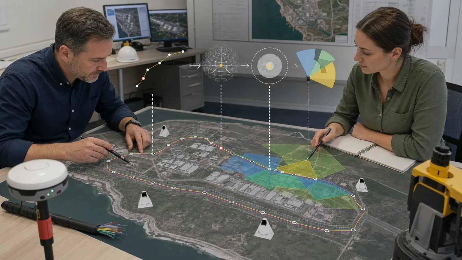
Fiber PIDS and DAS systems often report optical distance or calibrated chainage along a sensing route. Optical distance is not automatically the same as plan distance. Slack, loops, lead cable, splice allowance, reroutes, and calibration anchors can change the relationship.
Map chainage through a surveyed route geometry and a controlled calibration model. The model should identify route direction, origin, anchor points, offsets, discontinuities, loops, and the valid chainage range for each route revision. Use the fiber-optic PIDS cable-route design guide to keep the physical and logical route aligned.
A chainage event should carry the calibration and geometry revision used to derive its coordinate. If the current VMS map uses a different route revision, the integration should reject, translate through an approved migration, or visibly degrade the result instead of silently applying stale geometry.
Model Camera Coverage as Tested Visibility
An idealized radius or cone does not prove verification. Build coverage polygons from field observations at the required image quality, under the intended camera settings and operational conditions. The usable region may be irregular because of terrain, fence fabric, buildings, equipment, vegetation, lighting, glare, and seasonal change.
For each fixed view or PTZ preset, store the tested visibility polygon, camera and preset identity, mounting and lens configuration, day and night status, applicable image-quality purpose, occlusion notes, and validation date. Use the pixel-density planning guide to define the visual task instead of accepting a view that merely shows movement.
NPSA notes that PIDS zones need careful CCTV placement and perimeter lighting so the control room receives accurate information. Its PIDS guidance supports designing verification around the actual alarm location and operating environment.
Camera-Mapping Data Model
Event identity: source, channel, event ID, class, state, and original timestamp.
Spatial input: point, segment, zone, chainage, or coordinate plus the uncertainty model and geometry revision.
Route reference: route ID, direction, origin, calibration revision, valid range, and coordinate transformation.
Camera candidate: camera ID, fixed view or PTZ preset, visibility polygon, direction, image-quality role, and validation revision.
Operational state: online, degraded, obstructed, maintenance, preset available, PTZ busy, or failover active.
Selection result: primary view, secondary view, fallback overview, reason code, and mapping-policy version.
Evidence: selection timestamp, camera response, operator-visible view, exceptions, and acceptance result.
Where analytics metadata is exchanged through ONVIF, align the location and event fields with the tested Profile M perimeter-event contract. Profile M support does not replace the project route, uncertainty, camera coverage, or fallback model.
Select Cameras by Geometry and Operational Policy
First select cameras whose tested visibility intersects the alarm envelope. Then rank only those candidates by current availability, fixed or PTZ role, preset readiness, view direction, image quality, expected occlusion, operational priority, and fallback policy.
Camera-Selection Decision Matrix
Fixed camera fully covers the envelope: use it as the stable primary view when image quality and current health pass.
Several fixed cameras cover different parts: present a coordinated set or sequence instead of choosing one midpoint view.
PTZ preset covers the envelope: use it when the preset is validated, the camera is available, and contention policy permits movement.
Fixed overview plus PTZ detail: keep the fixed view visible during PTZ movement and use the PTZ for detailed assessment.
Primary camera offline or obstructed: select the tested fallback and visibly mark degraded verification.
No candidate covers the full uncertainty area: present partial views plus an explicit coverage exception; do not claim verified mapping.
Alarm falls on a mapping boundary: include candidates from both adjacent sectors according to the approved boundary tolerance.
PTZ is busy with a higher-priority event: retain the fixed or overview fallback and apply the documented arbitration rule.
Algorithm Flow
Validate the event. confirm source, state, timestamp, location type, coordinate basis, and mapping version.
Resolve the route. convert zone or calibrated chainage through the authoritative surveyed geometry.
Build the envelope. expand the point or segment by the validated location uncertainty and boundary tolerance.
Find spatial candidates. intersect the envelope with current field-tested camera visibility polygons.
Apply health and policy. remove unavailable views and rank fixed, PTZ, preset, direction, quality, and priority.
Present primary and fallback. open the selected verification view while preserving an overview or alternate path.
Record the decision. store the mapping version, selected cameras, reason, timing, degradation, and operator result.
Keep the spatial computation inside the overall PIDS detection and response-time budget. PTZ slew and settling are separate timing inputs; do not hide them inside an unmeasured camera association rule.
Design Boundaries, Overlaps, and Degraded Modes
Most mapping failures appear at transitions rather than zone centers. Test both sides of every zone boundary, shared corner, gate, route split, camera handoff, and survey revision. Define deterministic behavior when the alarm envelope touches several coverage polygons.
Duplicate or rapidly updated alarms should not cause cameras to oscillate between presets. Define event correlation, hold time, update handling, alarm-clear behavior, and PTZ contention rules. Keep the fixed overview available where practical. The fixed versus PTZ verification guide helps separate stable context from movable detail.
Missing or malformed coordinate
Chainage outside the calibrated route range
Stale route, camera, or preset revision
Camera offline, obstructed, or under maintenance
PTZ preset deleted, changed, or occupied by another event
No polygon intersection or only partial coverage
Map service, VMS, or integration failover active
Duplicate, late, or out-of-order event
Every degraded mode needs a safe fallback view, an operator-visible status, and evidence for maintenance. Silent substitution is not acceptable when it changes the area the operator can assess.
Field-Acceptance Checklist
Verify survey control, coordinate reference, axis order, units, datum, route direction, and geometry revision.
Test point, segment, zone, chainage, and missing-location events as applicable.
Test alarm centers, both sides of boundaries, corners, gates, overlaps, and route discontinuities.
Compare reported location, error envelope, selected camera polygons, and actual event position.
Validate each fixed view and PTZ preset during day, night, and relevant lighting or weather conditions.
Record terrain, fence, vegetation, equipment, glare, and seasonal occlusions.
Verify primary, secondary, overview, offline, obstructed, and PTZ-contention behavior.
Test stale mapping versions, invalid coordinates, duplicate events, updates, clear state, and failover.
Confirm the operator sees the correct physical sector and can complete the approved assessment task.
Preserve event records, map versions, coverage evidence, camera state, screenshots, video, deviations, and sign-off.
Implementation Note
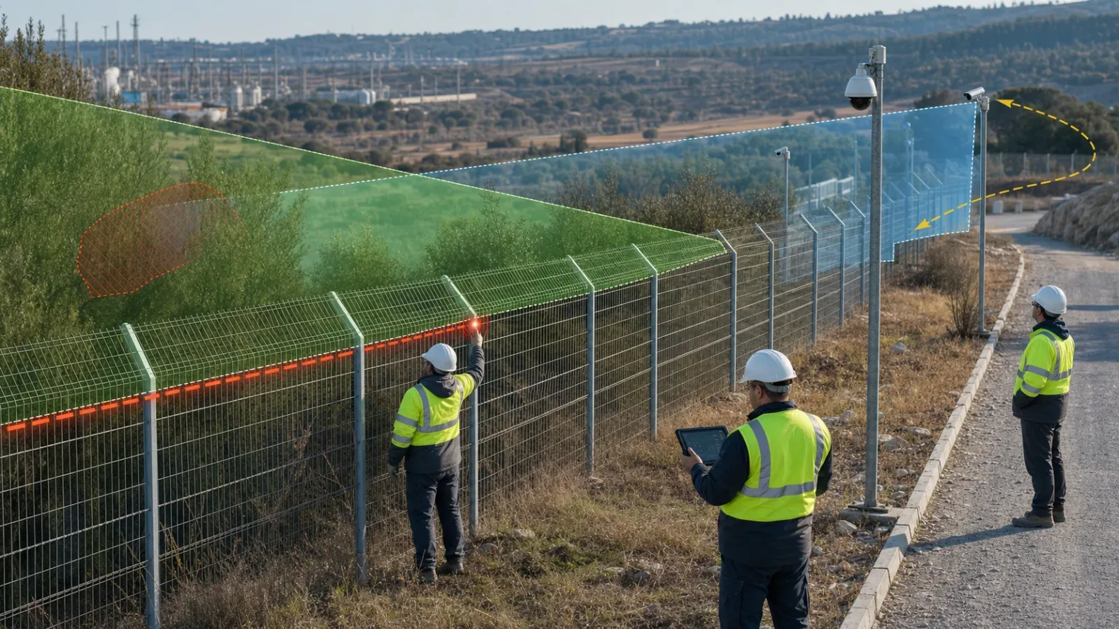
Treat the route model, camera coverage, presets, and selection policy as controlled configuration. Any fence reroute, fiber repair, camera move, lens change, vegetation growth, new structure, lighting change, firmware update, or VMS migration can invalidate part of the mapping.
Maintain a versioned matrix linking every perimeter segment to tested primary and fallback views. Revalidate affected polygons and boundaries after change, and schedule seasonal visibility checks where vegetation, snow, or sun angle can alter the image.
For high-consequence sites, connect the model to the wider critical-infrastructure perimeter architecture. Review how FortSense 4 supports zone and verification workflows, then request a mapping design review before freezing camera associations and acceptance tests.
Source and Scope Controls
PIDS zoning, verification, camera placement, and lighting context: NPSA PIDS guidance.
GeoJSON geographic coordinate basis and axis order: RFC 7946.
Analytics geolocation metadata context: ONVIF Profile M.
Advanced video and PTZ profile context: ONVIF Profile T.
Alarm-to-camera mapping can feed an enterprise SOC over a one-way boundary when local command remains on the trusted side. The data diode integration guide shows how to export mapped events without creating a reverse control path.
For border corridors, geospatial alarm mapping should be specified inside the broader border-security DAS design guide.
For nuclear sites, alarm-to-camera mapping should be specified inside the nuclear-facility PIDS design guide.