When overseeing the buildout of a new utility substation or data center expansion, security teams often face a gap between groundbreaking and the installation of permanent fencing. Construction phases demand robust yet flexible perimeter protection to deter theft of high-value materials, sabotage attempts, or unauthorized access amid shifting site layouts. The right temporary intrusion detection setup bridges this vulnerability without tying up resources long-term.
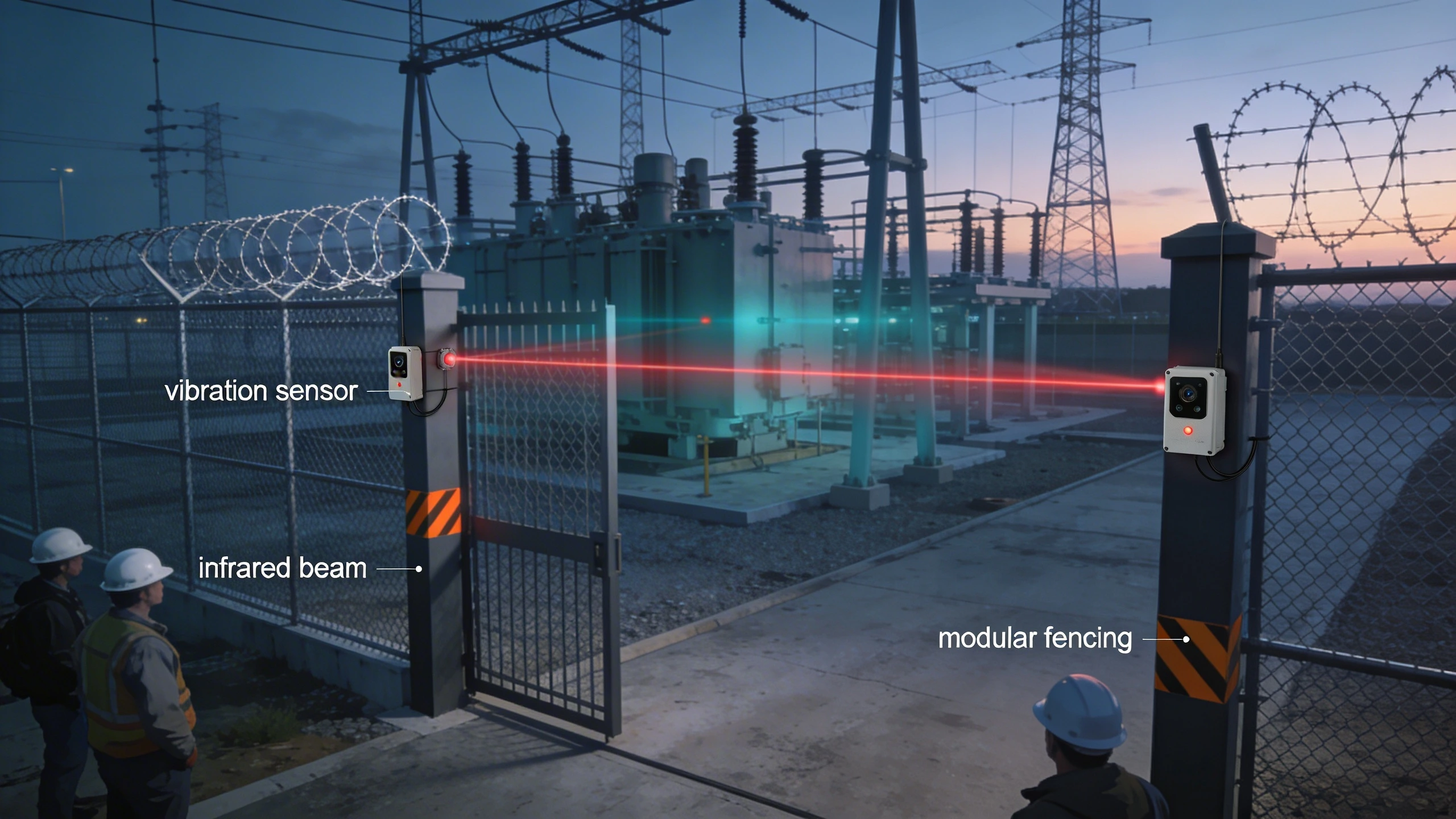
Integrators typically gravitate toward hybrid systems combining physical barriers like chain-link fencing with portable sensors—vibration detectors on posts, infrared beams across gates, or microwave barriers for open spans. This approach outperforms standalone cameras by providing immediate alerts on physical breaches, while allowing quick reconfiguration as excavation advances or scaffolding rises. In practice, tying these into a central monitoring station via wireless links ensures 24/7 coverage, even as crews rotate shifts.
For critical infrastructure projects, where downtime from incidents can cascade regionally, the design decision hinges on balancing detection range, false alarm resilience, and ease of teardown. A well-chosen system not only covers the current footprint but scales for phased handoffs to permanent Perimeter Intrusion Detection Systems, minimizing reconfiguration costs.
What the design decision looks like in practice
On a typical greenfield substation site spanning several acres, temporary perimeters start with modular fencing panels clipped together to enclose equipment laydown areas and active work zones. Sensors mount directly to fence fabric or posts: coaxial cable stretched taut for vibration sensing picks up climbs or cuts, while point detectors at corners flag leaning or cutting tools. Gaps at vehicle entries get beam stacks or swinging-gate detectors, ensuring no blind spots as dozers reposition daily.
During peak construction, when night shifts guard against copper wire theft—a common target—operators configure zones via a mobile app, silencing alerts near crane paths while arming high-risk transformer pads. As concrete pours and structures rise, sections migrate inward, with sensors redeployed to protect elevated platforms. This fluidity distinguishes temporary designs from fixed ones, demanding components rated for dust, rain, and temperatures swinging from subzero to scorching.
Real-world example: a Midwest wind farm expansion used battery-backed IR towers for 200-meter spans between turbine bases, integrating alerts into existing SCADA for automated lockdowns. Crews reported under 1% nuisance alarms after tuning, proving the setup's viability for remote sites.
System architecture and integration considerations
Core architecture revolves around a distributed edge network: field panels aggregate sensor data over RS485 or wireless mesh, feeding a ruggedized gateway for IP uplink to a PSIM or VMS. For construction transience, prioritize PoE-plus or solar-powered nodes to sidestep trenching power lines amid ongoing grading. Microwave or active IR sensors suit long, unobstructed runs, while fiber-optic distributed sensing handles irregular terrain but requires splicing expertise.
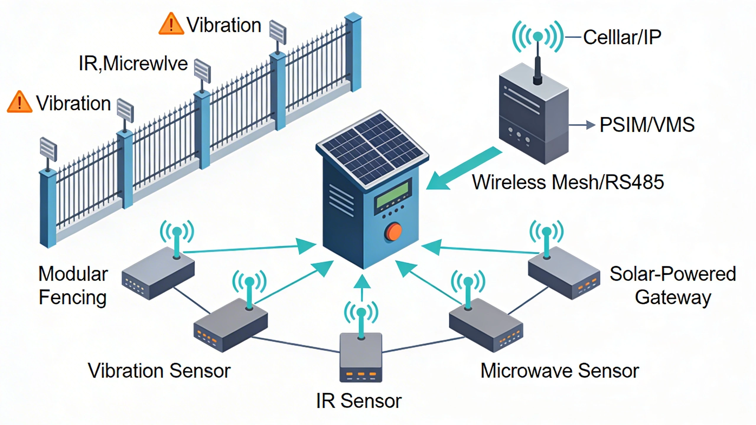
Integration challenges arise with legacy site systems. Wireless protocols like LoRaWAN offer low-power range but demand careful channel planning to avoid interference from welding radios. Link to PSIM platforms enables correlation—pairing a fence hit with PTZ camera slew—reducing operator fatigue. Scalability matters: start with 20-50 sensors, provision for doubling as the site densifies.
Tradeoffs include wired vs. wireless: cabling survives heavy equipment better but slows relocation; wireless eases moves yet risks jamming. Hybrid gateways bridge both, routing via cellular failover for sites without fiber.
Operational workflows and field constraints
Daily ops begin with pre-shift patrols to verify sensor alignment, followed by arming sequences tailored to crew schedules—daytime stand-down for welders, full arm at dusk. Technicians use handheld configurators for zone tweaks, logging changes against blueprints to track evolving layouts. Alarm verification flows through video pop-ups or drone dispatch, with escalation to site security within 60 seconds.
Field constraints dominate: mud-clogged gates demand elevated mounts, wind gusts trigger beam falses unless stabilized. Power management is key—solar arrays with deep-cycle batteries sustain weeks without grid tie-in, monitored via SNMP for low-charge alerts. Training emphasizes rapid breakdown: panels unclip in minutes, sensors pack flat for storage.
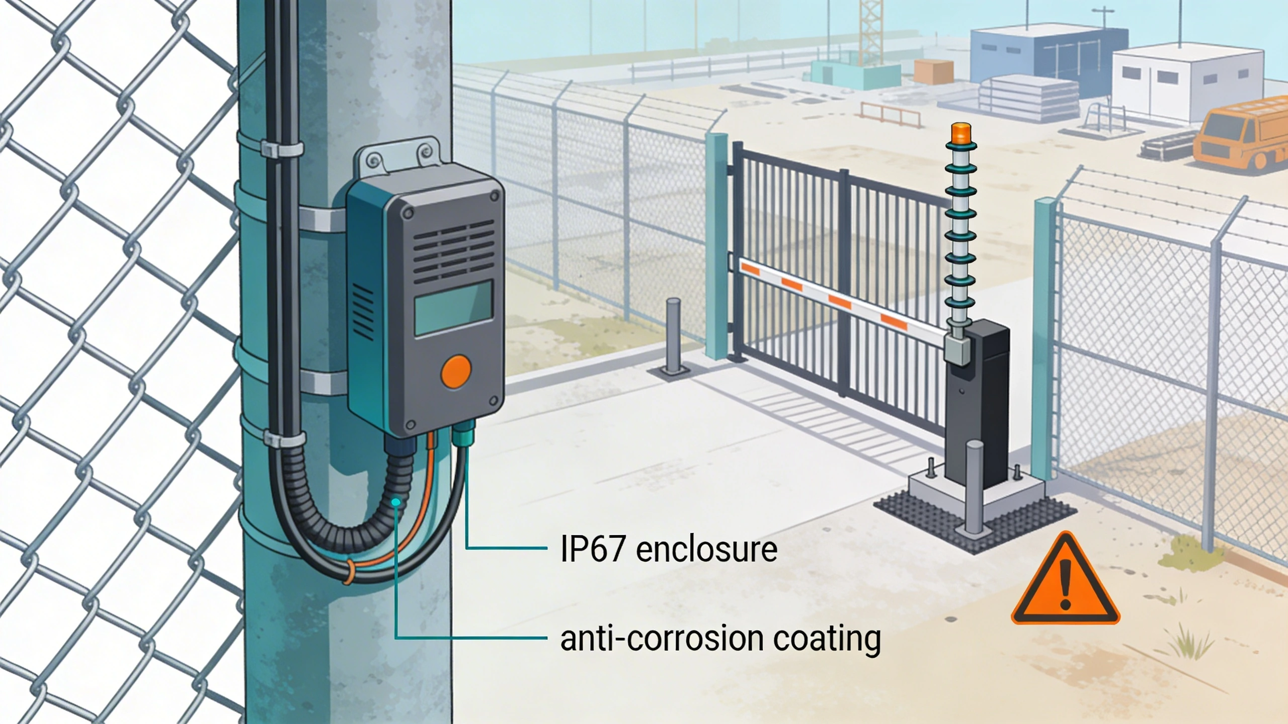
In harsh environments like coastal builds, IP67 enclosures and anti-corrosion coatings prevent downtime. Workflow integration with construction management software flags secure zones for subcontractor access, streamlining compliance audits.
Common failure points and design mistakes
Overlooking terrain leads to shadowed coverage: low spots flood, masking IR paths, or berms block microwaves. Mistake here cascades to undetected breaches. Another pitfall: underspeccing power for winter sites, where batteries drain fast, leaving gaps.
Poor integration silos alerts—fence ping ignored amid camera floods. Designers fix this with unified dashboards, but skipping latency tests dooms remote verification. Sensor overload from construction noise (hammers, generators) spikes falses; improper filtering wastes response time.
- Neglecting modular mounting: rigid installs shatter under fence flex.
- Ignoring scalability: fixed processor limits zone adds.
- Forgetting teardown: proprietary connectors trap gear onsite.
What to verify before procurement
Request environmental specs matching site extremes—vibration tolerance, ingress protection, operating range. Probe detection probabilities across scenarios: cut, climb, dig. Confirm wireless certs (FCC Part 15) and interoperability with ONVIF or your PSIM.
Evaluate relocation speed: demo a full zone move in under 30 minutes. Scrutinize power draw and recharge times; demand MTBF data from field deployments. Check vendor support for construction cycles—firmware OTA updates without site visits.
- Sensor range proofs on mock fences.
- Failover demos: cut power, lose signal.
- Third-party integration logs.
Where to go next
Explore FortSense 4 for scalable perimeter solutions tailored to critical sites. For custom designs, request a design review. Learn more about critical infrastructure security applications or North America deployments.