When upgrading perimeter security at a utility substation or expansive campus, the cable route for a fiber optic Perimeter Intrusion Detection System (PIDS) becomes a pivotal design choice. These systems turn standard fiber optic cables into continuous vibration sensors, capable of pinpointing disturbances like climbing, cutting, or digging across kilometers of perimeter. Integrators must weigh terrain challenges, existing infrastructure, and nuisance alarm risks from wind-swept fences or passing trains against the need for uniform sensitivity.
Buried cable routes parallel to the fence line, offset by one to two meters, provide stealthy coverage ideal for greenfield sites or tamper-prone areas, but they require coordinated trenching around utilities and precise backfill to transmit ground vibrations effectively. In contrast, attaching the cable directly to chain-link or welded mesh fences accelerates retrofit timelines, leveraging the fence fabric itself as a disturbance amplifier—though secure fastening is non-negotiable to prevent sagging under weather exposure. Selecting the route that aligns with site geometry and operational tempo often yields the most reliable zone definitions and lowest maintenance burden.
Site surveys reveal that hybrid approaches, combining buried segments through vegetated zones with fence-mounted runs along open gates, optimize overall performance without excessive splicing. This upfront routing decision influences everything from interrogator placement to integration with PSIM platforms, ensuring alarms correlate precisely with video assessments.
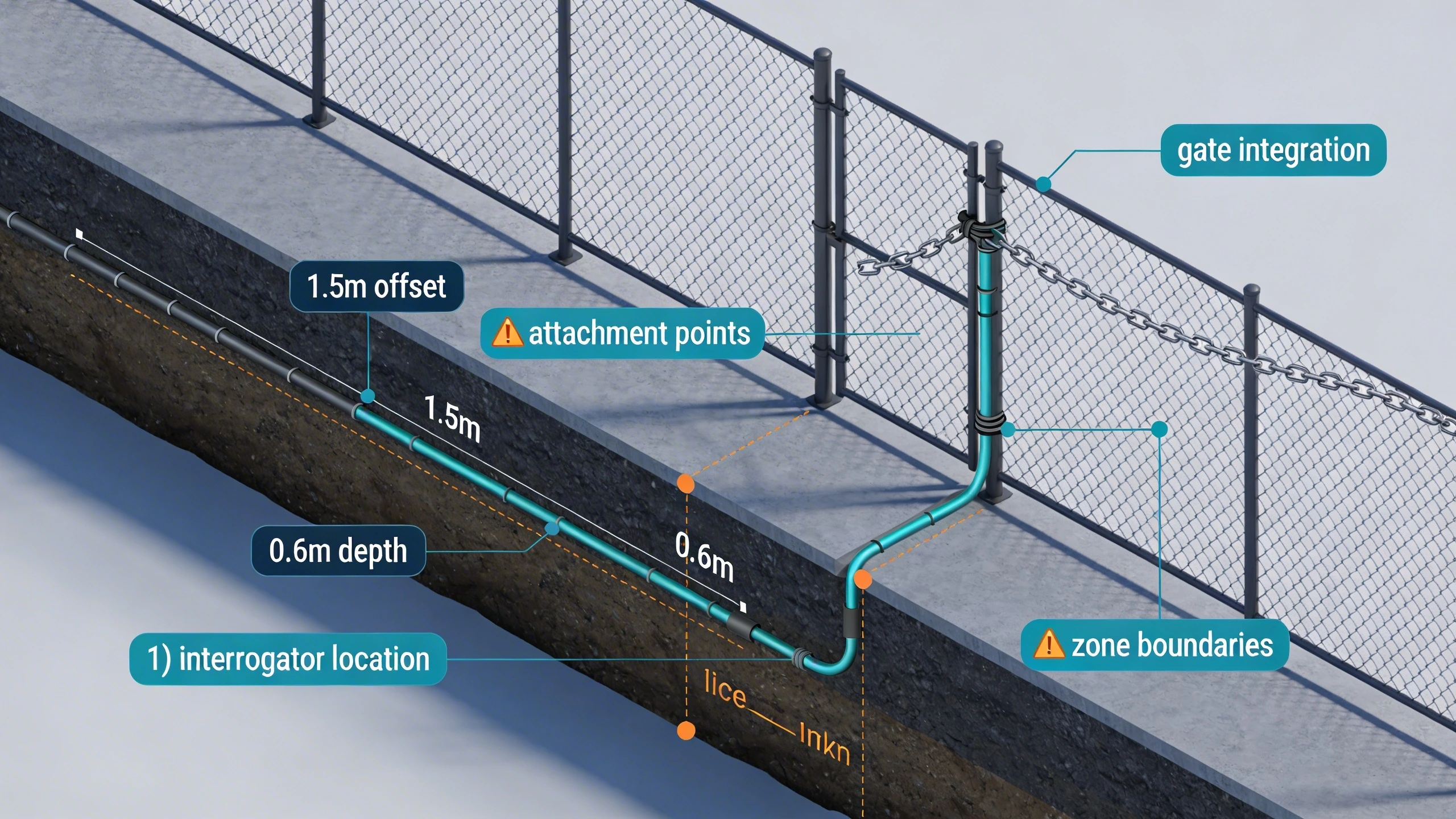
What the design decision looks like in practice
Picture a 2 km perimeter around a data center campus: the design team opts for a buried route along chain-link sections prone to vehicle proximity, trenching 0.6 meters deep in sandy soil to capture digging attempts while damping road noise. Transitioning to fence attachment at the gated entry, they secure the cable with UV-resistant ties every 50 cm, running it horizontally midway up the fabric to maximize climb detection. This mixed topology allows software-defined zoning—say, 250-meter segments—calibrated distinctly for soil versus metal propagation characteristics.
During commissioning, technicians walk-test each zone, simulating cuts and lifts to map response patterns. The route's straight-line fidelity minimizes attenuation hotspots, preserving signal-to-noise ratios over the full length. Field teams report that such deliberate routing cuts nuisance alarms by aligning cable paths away from sway-prone trees or expansion joints, a lesson hard-learned from earlier pilots where meandering trenches amplified irrelevant vibrations.
In multi-site rollouts, like securing North America deployments, standardized route templates emerge: offset burial for rural stretches, vertical fence runs for urban walls. These practices scale reliably, adapting to local soils without reinventing calibration profiles.
System architecture and integration considerations
Fiber optic PIDS architectures center on a central interrogator launching laser pulses down the single-ended cable, analyzing backscattered light for micro-vibrations. Route design dictates processor siting—ideally within 1-2 km of the start to limit lead-in fiber loss—and zoning logic, where software partitions the linear cable into virtual segments for granular alarming. Dual-fiber loops enhance cut immunity in high-threat zones, doubling back along the same path but requiring mirrored routing precision.
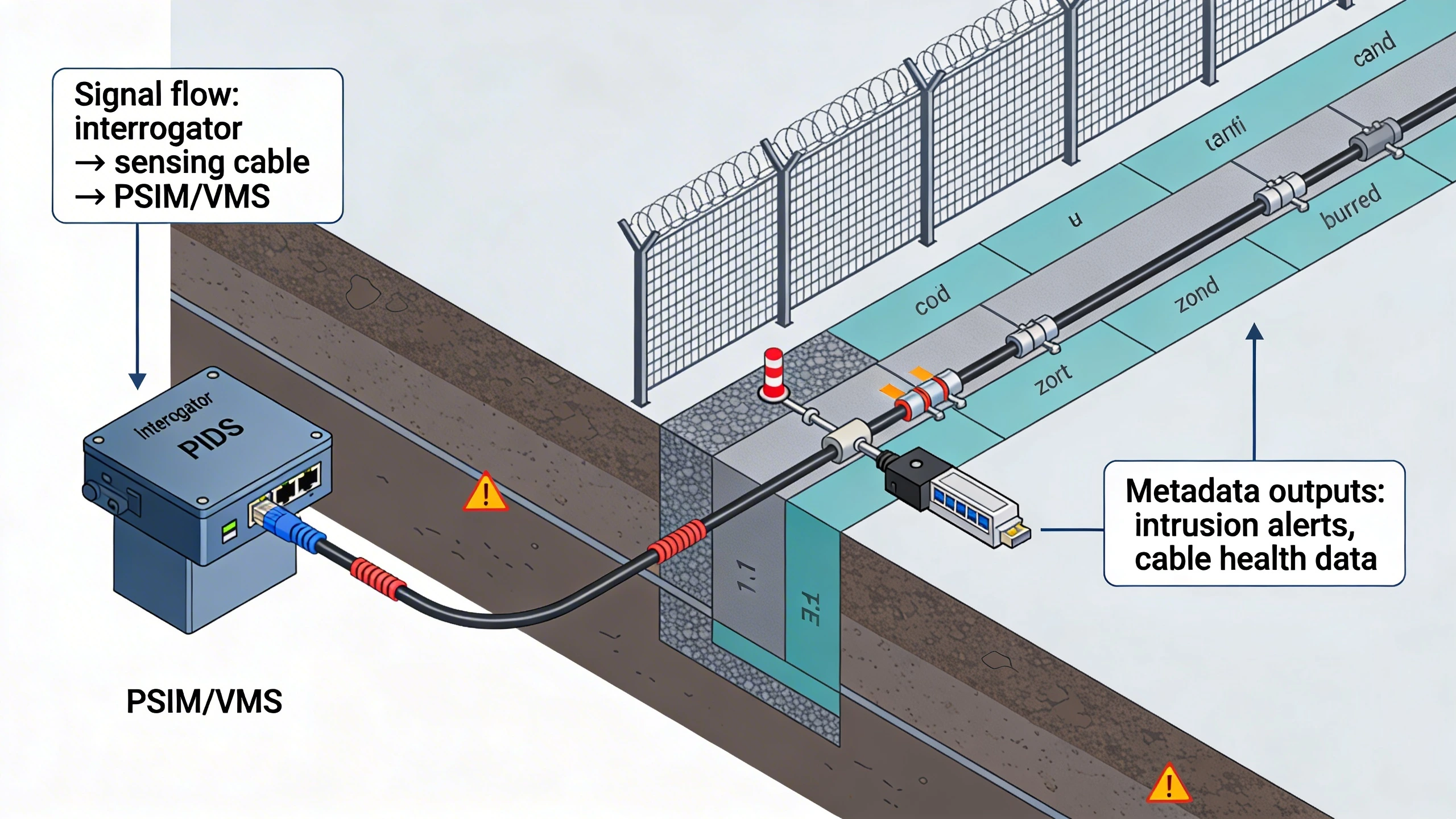
Integration demands forethought: route the non-sensing lead-in cable through secure conduits to the PSIM headend, supporting Ethernet or fiber uplinks for real-time metadata like intrusion coordinates. Gateways at route transitions enable hybrid sensing with IR cameras, fusing cable alerts with visuals. Poorly planned routes complicate this, as splices introduce latency or dead zones, forcing oversized zones that blur pinpoint accuracy.
For FortSense 4 ecosystems, route layouts feed directly into dashboard maps, overlaying cable paths on GIS layers for operator intuition. This visibility streamlines third-party VMS handoffs, where a climb on a precisely routed fence segment triggers PTZ slews without ambiguity.
Operational workflows and field constraints
Pre-installation workflows kick off with geophysical surveys, potholing utilities to dodge buried lines that could sever cables or inject EMI crosstalk. Trenching follows contour lines for burial routes, maintaining 30-100 cm depths suited to soil type—shallower in clay for better dig sensitivity, deeper in loose gravel against animal burrows. Fence attachments demand tension checks, torquing ties to spec before environmental exposure warps the profile.
Field constraints like rocky outcrops or flood-prone dips force deviations: elevated conduits over washes preserve continuity, while segmented burial skips impassable berms. Maintenance patrols standardize on route markers every 100 m, easing fiber integrity tests with OTDR tools. Operators train on seasonal recalibrations, tweaking thresholds as frozen ground alters propagation versus summer digs.
Retrofit workflows prioritize minimal downtime, splicing live segments overnight. Constraints such as heritage fences cap attachment heights, shifting reliance to ground-level burial hybrids that workflows document via as-built diagrams.
Common failure points and design mistakes
Sharp bends exceeding 20x cable diameter crush fibers, spiking attenuation and creating blind spots that evade cut detection. Designers err here on tight corners, mistaking armored sheathing for bend immunity—post-install OTDR traces expose these ghosts. Similarly, inconsistent burial depths yield patchy sensitivity, where shallow runs scream at rain while deep sections miss footsteps.
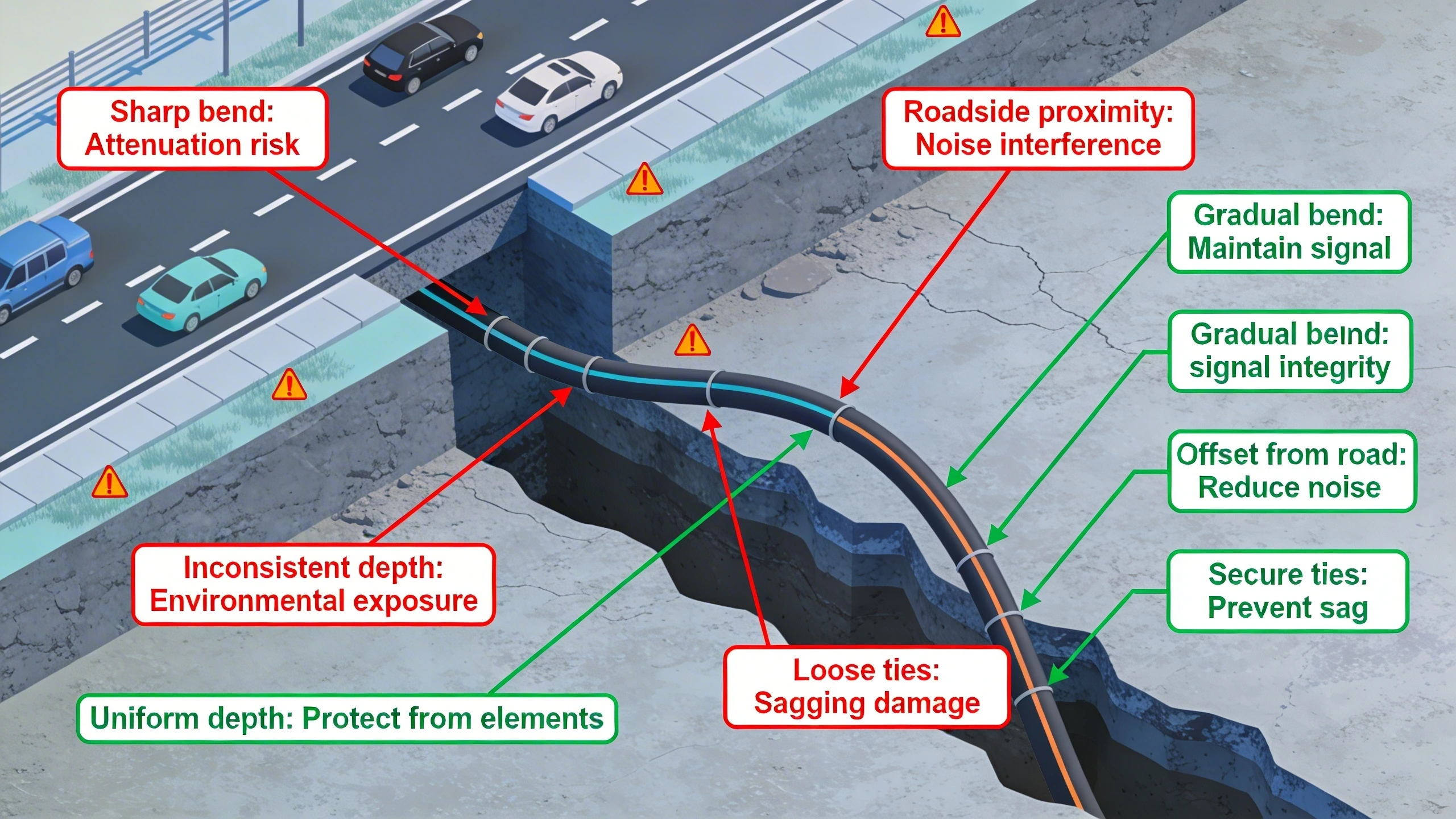
Proximity to vibration sources plagues routes hugging roadsides; offset burial mitigates but demands buffer zoning. Loose ties on fences allow sag, decoupling the cable from disturbances and inflating false negatives. Splice enclosures exposed to moisture corrode, fracturing signals mid-route—a mistake amplified in unzoned long hauls.
- Verify minimum bend radii across all transitions, including gate swings.
- Model nuisance paths pre-trench, buffering high-traffic adjacencies.
- Audit tie tension and burial compaction during QA walks.
What to verify before procurement
Confirm cable specs match interrogator wavelengths—1550 nm single-mode with tight-buffered, direct-burial armor for versatility across routes. Probe vendor data on max sensing length per channel, ensuring it envelopes your perimeter without excessive repeaters that dilute zoning. Review deployment case studies for your fence type, validating Pd/Nu rates on comparable soils.
Site-specific verifications include terrain modeling for optimal offsets and utility overlays to preempt reroutes. Prototype a 100 m test loop mimicking your hybrid path, quantifying alarm profiles under wind and digs. Budget for redundant cores if cut-resilience trumps cost, and confirm PSIM SDKs align with your route metadata outputs.
Procurement checklists extend to service life projections under UV/chemical exposure, plus training mandates for your team's route commissioning rituals.
Before constructing a new sensing route, determine whether installed unused strands pass the dark-fiber reuse feasibility and POC process.
Where to go next
Once the physical route is approved, convert the cable route into a fence-retrofit BOM that traces every cable length, attachment, gate assembly, enclosure, interface, and test deliverable.
Where the sensing route follows chain-link fabric, continue into the chain-link fiber PIDS attachment design for host-fence acceptance, secure-side routing, transitions, protection, and field testing.
Deploying fiber optic PIDS demands precision tailored to your perimeter's realities. Explore FortSense 4 for integrated sensing platforms, or dive into critical infrastructure security strategies. For expert input, request a design review.
Where the route follows rigid fence panels, apply the welded-mesh fence installation design to the panel, post, seam, and protected-crossing details.
Link the controlled route and chainage revision to the geospatial alarm-to-camera mapping model so later reroutes cannot silently point verification at stale geometry.