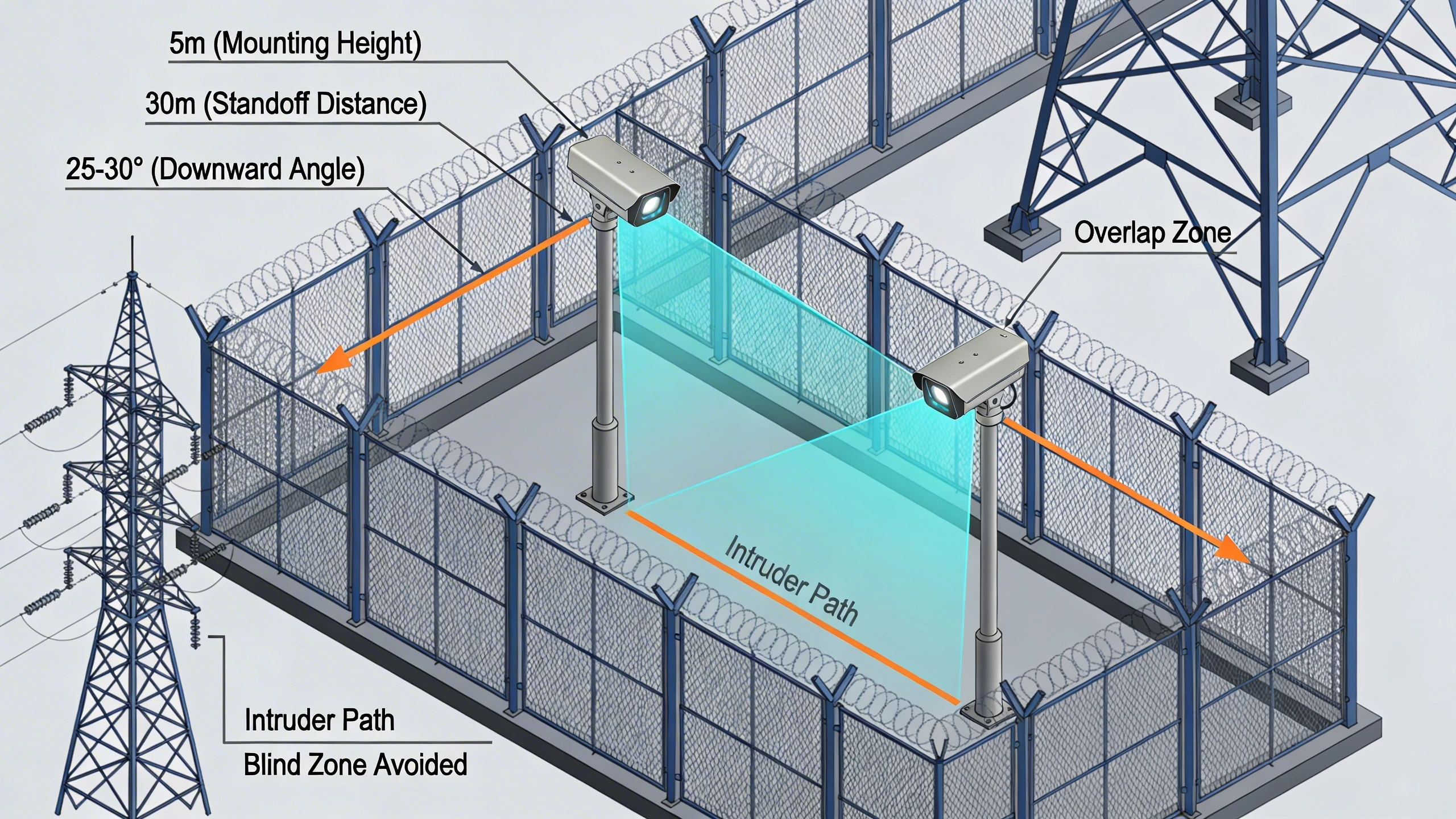
When retrofitting a utility substation's perimeter fence with thermal cameras, integrators face immediate choices about pole heights and camera positioning relative to the intrusion line. Too low a mount invites tampering and ground clutter false alarms from animals or vegetation; too high sacrifices resolution on human-sized targets. Similarly, standoff distance—the lateral separation between camera and protected boundary—must align with the lens field of view to cover adequate fence length while maintaining pixel density for reliable analytics triggers. These decisions, often overlooked in favor of range specs, determine whether the system alerts operators to real threats or floods them with noise.
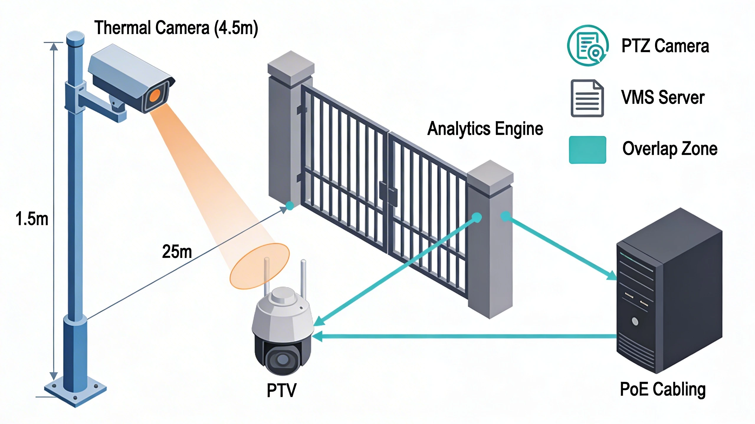
Consider a multi-building campus upgrading entry gates for 24/7 monitoring. Existing visible-light cameras struggle in fog or at night, prompting a shift to thermals paired with video management software. Here, mounting at 4 to 6 meters allows a steep downward angle that minimizes sky exposure—reducing solar hot spots—while positioning cameras 20 to 50 meters inside the fence ensures targets cross the field of view horizontally for optimal detection probability. This configuration, drawn from established perimeter practices, balances coverage, analytics accuracy, and physical security without relying on unproven long-range claims.
Security managers evaluating these upgrades appreciate how such placements integrate with existing poles or masts, avoiding full infrastructure overhauls. The upfront modeling of height and standoff pays dividends in reduced nuisance alarms and faster verification workflows, especially in critical infrastructure where downtime equates to vulnerability.
What the design decision looks like in practice
In a typical perimeter retrofit, like securing a 500-meter utility fence line, teams select mounting heights starting at a minimum of 4 meters to enable a pronounced downward tilt. This elevation clears ground-level obstructions such as brush or small animals, which thermal sensors might otherwise mistake for intruders due to their heat signatures. The camera's field of view then fans out parallel to the fence, with the standoff distance calibrated so a human crossing perpendicularly occupies sufficient pixels—often aiming for at least 1.5 pixels across the target's critical dimension for basic detection, per longstanding thermal imaging criteria.
For gate or doorway applications in a warehouse complex, heights drop to 2.5 to 3.5 meters above the threshold, focusing on close-range classification where recognition demands more pixels on facial or torso regions. Standoff here is minimal, perhaps 5 to 10 meters, to capture tailgating or loitering without foreshortening distortion. Integrators model these using manufacturer nomographs or simulation tools, adjusting for lens focal length: narrower fields suit longer standoffs for sparse perimeters, while wider ones cover busier approaches. Field trials confirm the setup, walking simulated intruders to verify alarm thresholds.
These choices manifest during installation as precise pole guy-wiring and bracket angles, ensuring stability against wind that could jiggle the view and trigger motion analytics erroneously. Operators gain confidence knowing the system prioritizes threats moving across the scene rather than toward or away, a nuance that elevates thermal deployments beyond point-and-shoot installs.
System architecture and integration considerations
Integrating thermal cameras into a broader surveillance architecture requires aligning mounting parameters with network video recorders, analytics engines, and PTZ spotters. A high mount at 5 meters, for instance, complements a visible PTZ verifier by providing early warning across a 100-meter fence segment, with standoff ensuring the thermal FOV hands off cleanly to the slave camera's zoom. This layered approach leverages thermal's weather immunity while using visible light for positive ID, all orchestrated via ONVIF-compliant VMS platforms.
Tradeoffs emerge in cabling runs: taller poles demand longer Ethernet drops, potentially necessitating mid-span PoE injectors or fiber for distances beyond 100 meters. Standoff influences switch placement too—cameras 30 meters in from the boundary might route back to hardened edge devices in enclosures, mitigating EMI from nearby power lines common in utility sites. Firmware compatibility matters; mismatched analytics rules can ignore height-induced scale variations, leading to dropped classifications.
Designers also weigh multi-sensor heads, where thermal and visible share a mount. Uniform height simplifies calibration, but standoff must suit the wider FOV component, often dictating conservative spacing that underutilizes the thermal's potential range. Pre-staging these in a lab mockup reveals synchronization quirks before site deployment.
Operational workflows and field constraints
Day-to-day operations hinge on mounts that facilitate maintenance access without scaffolding every lens clean. A 4-meter height strikes a balance: reachable with lifts for quarterly wipes against dust or pollen that degrade IR transparency, yet tamper-resistant for roaming patrols. Standoffs over 20 meters keep gear away from fence climbers, allowing ground teams to inspect without entering the FOV and spiking false alerts.
Field realities like uneven terrain or legacy pole spacing force compromises. On sloped substations, effective height varies, requiring tilt adjustments to maintain consistent ground coverage—too shallow an angle leaves dead zones under the camera, too steep clips distant targets. Wind loads amplify at height; undersized masts vibrate, blurring analytics that demand crisp edges for rule-based detection.
Workflows improve with mounts enabling overlap: adjacent cameras at matched heights and standoffs create seamless handoffs, letting operators track intruders via a single pane without stitching feeds manually. Seasonal foliage growth encroaches on standoff margins, prompting annual surveys to prune or relocate for sustained performance.
Common failure points and design mistakes
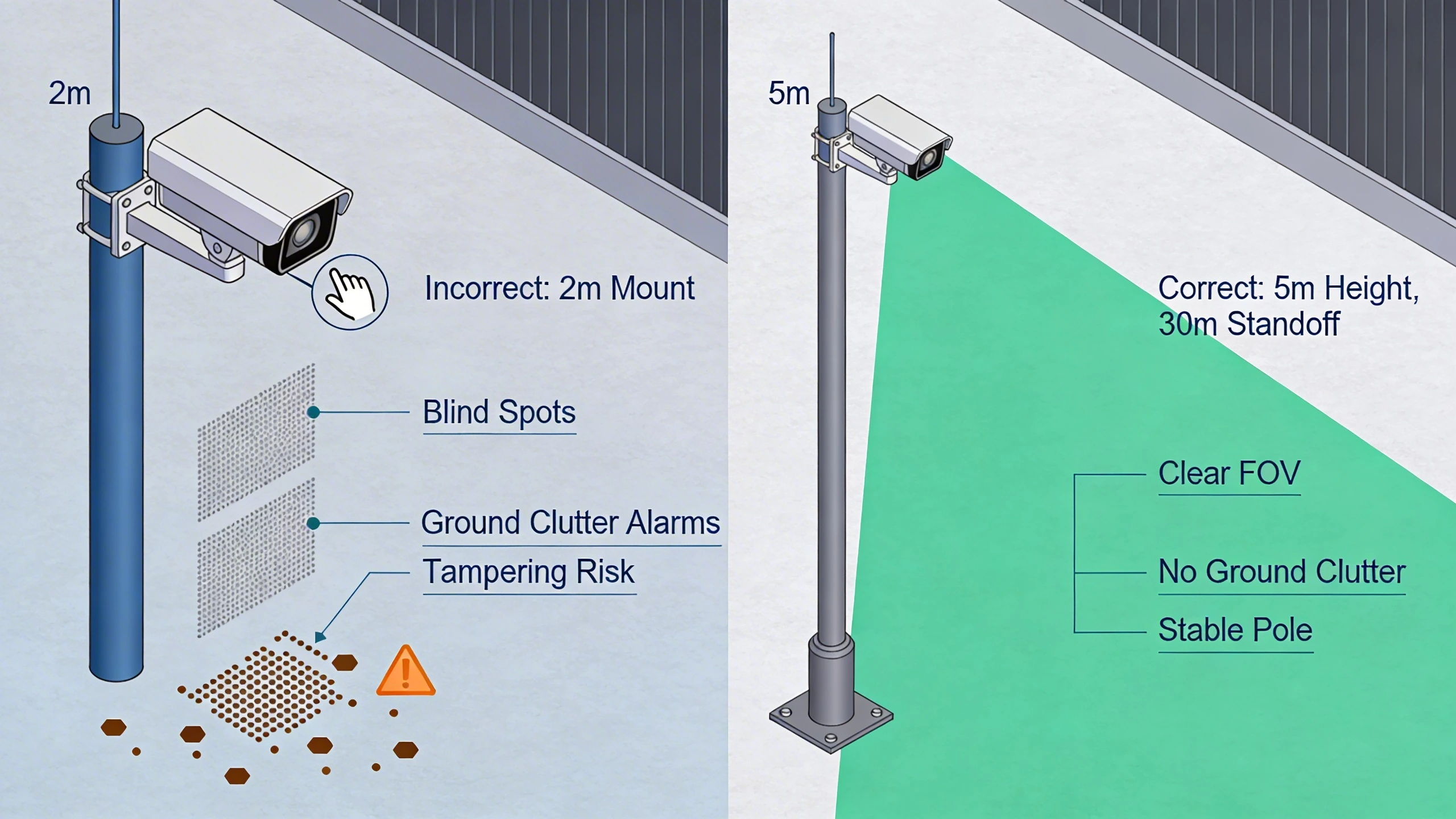
One prevalent error mounts thermals too low—under 3 meters—inviting direct sabotage and overwhelming sensors with clutter like rabbits or rain puddles mimicking human heat. The resulting alarm fatigue erodes trust, with operators muting feeds and missing genuine breaches. Conversely, excessive heights beyond 8 meters foreshorten distant figures, dropping pixel counts below detection thresholds and rendering analytics useless for small targets like children or drones.
Misjudged standoff plagues linear deployments: too close, and the narrow FOV leaves fence gaps; too far, and resolution suffers, especially in adverse weather where temperature deltas shrink. Installers often default to manufacturer max ranges without site-specific modeling, ignoring background uniformity—hot roofs or roads bleed into scenes, fooling classifiers.
Vibration from unstable mounts or nearby traffic introduces motion ghosts, while ignoring tilt leads to sky glare hotspots that saturate detectors. Retrofitting without verifying pole load ratings risks failures mid-storm, underscoring the need for structural audits pre-install.
What to verify before procurement
Before specs lock in, confirm lens options match projected standoffs via range calculators, ensuring sufficient pixels on targets at worst-case distances. Request environmental specs: IP ratings for height-exposed housings and heater viability for sub-zero ops at elevation.
Probe integration: Does the model support edge analytics tolerant of height-induced scale? Check mounting kits for your pole diameters and wind zones. Field-test samples for background rejection in your locale's conditions.
- Validate min/max tilt ranges suit your angles.
- Assess power budgets for tall installs.
- Review warranty on vibration-induced defects.
Where to go next
Explore FortSense 4 for analytics-ready thermal integration in high-assurance environments. For tailored advice on your site, request a design review. See applications in critical infrastructure security and North America deployments.