When overseeing security for a distributed portfolio like regional utility substations or a multi-building campus, the shift from siloed, site-specific systems to a cohesive multi-site architecture often arises during expansions or compliance-driven retrofits. Integrators frequently encounter this when consolidating oversight for a dozen perimeter gates, camera feeds, and access points across remote locations, where local controllers handle real-time decisions but feed into a central analytics layer. The core design pivot centers on layering centralized policy enforcement over autonomous edge processing, ensuring that a compromise at one substation doesn't cascade while maintaining unified threat visibility.
This approach shines in retrofit scenarios, such as linking legacy door controllers at an industrial park with modern video management across fiber-connected sites. Rather than ripping out hardware, teams map existing endpoints to a federated model, prioritizing protocols that bridge vendor gaps without overhauling cabling. Early decisions here dictate long-term scalability: opt for rigid centralization, and bandwidth bottlenecks emerge during peak events; lean too decentralized, and policy drift undermines compliance audits. Grounded in field realities, these architectures demand balancing latency-sensitive local actions with aggregated intelligence.
For security managers and IT leads, the upfront architecture choice influences everything from incident response speed to maintenance costs. A well-structured multi-site setup, for instance, allows a single operator console to correlate door denial events from a remote pump station with anomalous video from headquarters, flagging coordinated intrusions faster than disjointed alerts.
What the design decision looks like in practice
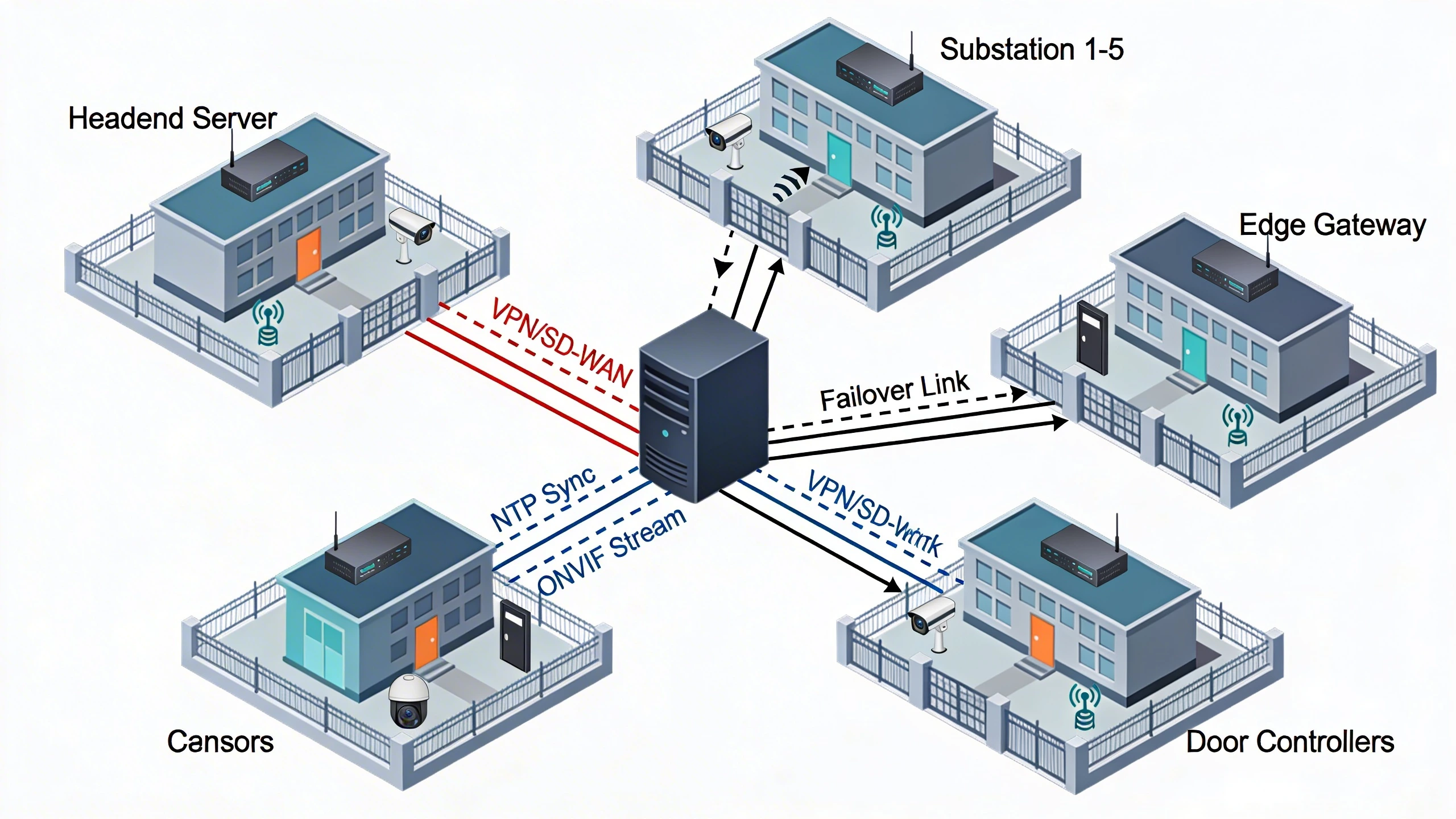
In a typical retrofit for a North America-based energy provider spanning five substations, the design manifests as a hub-and-spoke topology where each site runs edge appliances for access control and video ingest, synchronized to a regional headend server. Operators configure global policies—like badge expiration rules or camera retention—once at the headend, which pushes them via secure tunnels to sites, overriding local defaults only during overrides. This setup proved effective during a recent expansion, where integrators overlaid new intrusion sensors without disrupting 24/7 operations, using modular gateways to normalize data flows from disparate panel vendors.
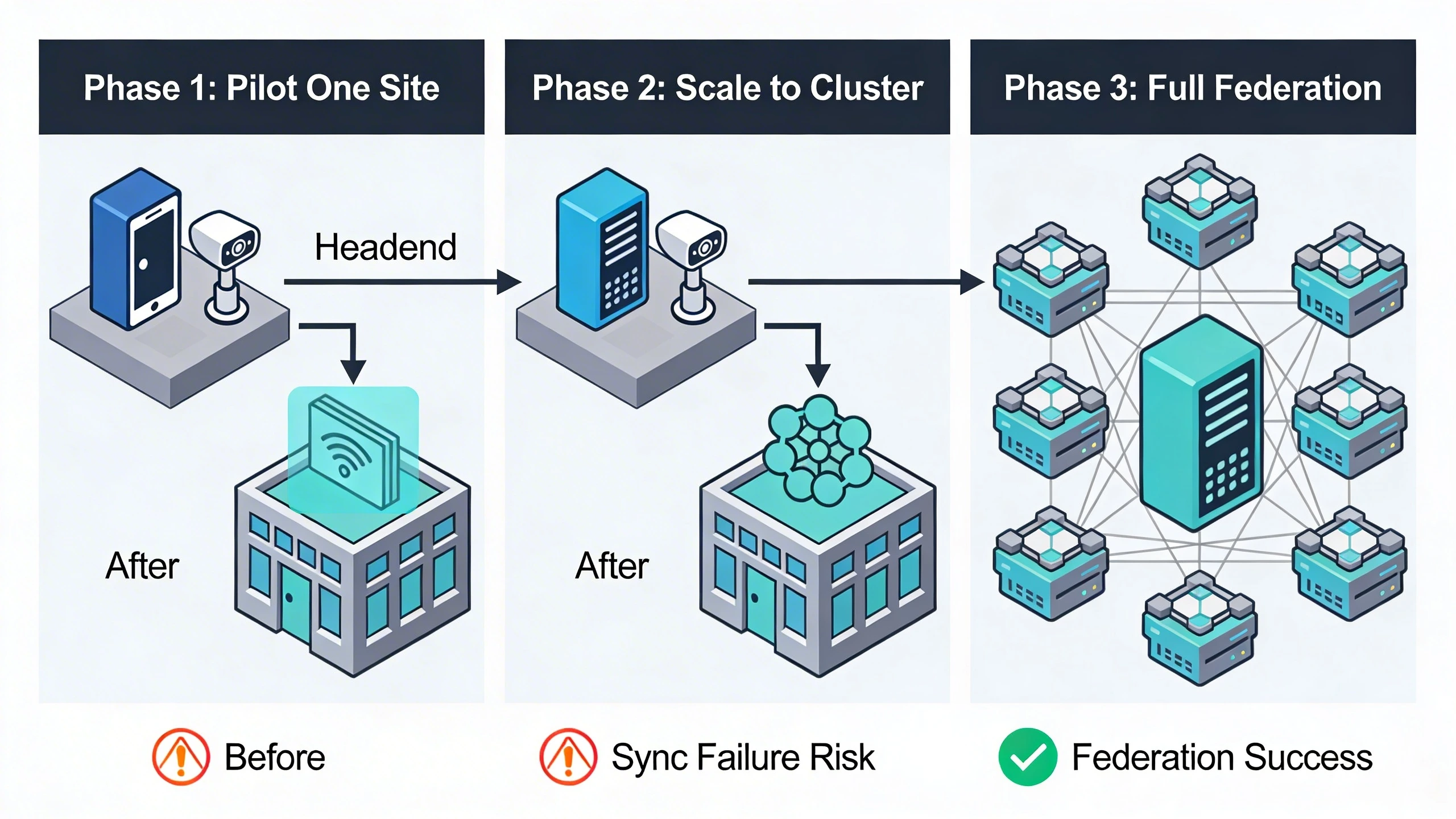
Contrast this with a campus environment, such as a university with dorms, labs, and athletic facilities. Here, the architecture evolves into zoned clusters: each building acts as a semi-autonomous node with its own failover redundancy, linked through a core switch fabric. During implementation, teams stage migrations by piloting one zone—say, integrating 50 doors and 200 cameras—validating cross-site event correlation before scaling. The decision favors containerized VMS deployments on standard servers, allowing seamless scaling as sites add endpoints without custom hardware procurements.
Practically, this means diagramming data paths upfront: edge devices poll headend for updates every 15 minutes, while critical alerts stream in real-time over encrypted channels. Field crews appreciate the modularity, as it supports brownfield installs where power constraints limit on-site compute.
System architecture and integration considerations
At the heart of multi-site designs lies robust networking, often leveraging VPN overlays on existing MPLS or SD-WAN fabrics to isolate security traffic from operational data. Integration hinges on standards like ONVIF for device discovery and streaming, ensuring cameras from multiple makers join the pool without proprietary SDKs. For time-sensitive correlation—vital when timestamping a door event against video—NTP hierarchies anchor local clocks to GPS-stratum sources, preventing drift that could invalidate forensic chains.
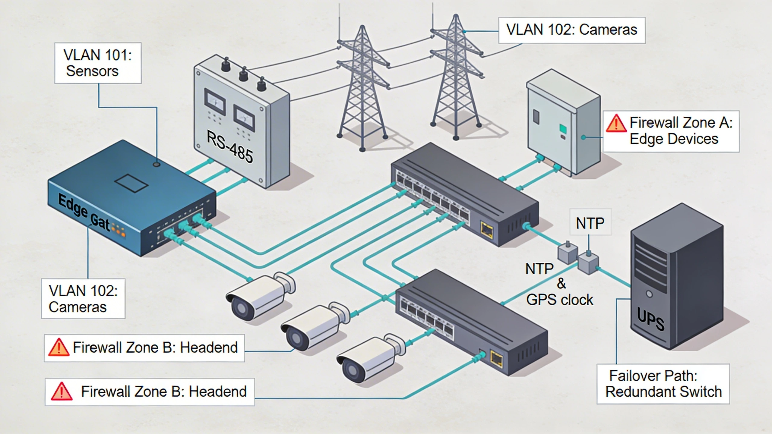
Consider a utility retrofit: sites connect via 4G/5G failover to a private cloud edge, with gateways handling protocol translation for legacy RS-485 panels. This decouples physical layers from analytics, allowing IT managers to virtualize headends on hypervisors while integrators focus on endpoint hardening. Tradeoffs emerge in redundancy: full-mesh peering adds resilience but spikes config complexity, whereas hierarchical models streamline management at the cost of potential choke points during surges.
Scalability tests reveal bandwidth as the silent killer; a single 4K stream per camera multiplies across sites, so compression and multicast routing become non-negotiable. Successful integrations profile traffic patterns pre-deployment, throttling non-essentials to preserve forensic-quality feeds.
Operational workflows and field constraints
Daily operations in multi-site environments revolve around unified consoles that aggregate dashboards, where a security operator at headquarters reviews live maps pinning incidents across sites. Workflows adapt for field realities: remote firmware updates roll out in maintenance windows, sequenced site-by-site to avoid outages, while mobile apps empower technicians to acknowledge local faults without full VPN logins. In a campus scenario, this means badge audits sync bidirectionally, letting dorm staff issue temp credentials that propagate instantly enterprise-wide.
Field constraints shape everything—intermittent rural bandwidth demands local buffering for video clips, queued until links recover, while harsh environments call for NEMA-rated enclosures with PoE extenders. Integrators learn quickly that ignoring solar variability at off-grid sites leads to battery drains during extended clouds, so designs incorporate UPS sizing based on duty cycles. Operator training emphasizes cross-site drills, simulating a perimeter breach at one substation triggering lockdowns elsewhere.
Incident response workflows leverage predefined escalations: automated notifications chain from local alerts to regional SOCs, with playbooks dictating evidence pulls from distributed archives. Constraints like varying local regulations force geo-fencing policies, ensuring compliance without blanket overreach.
Common failure points and design mistakes
One prevalent pitfall is underestimating synchronization latency, where NTP misconfigs cause event timelines to skew by seconds, complicating legal reviews or AI analytics that rely on precise sequencing. In a multi-building retrofit, teams overlooked VLAN segmentation, exposing control traffic to guest Wi-Fi, which escalated a simple scan to a full incident. Another mistake: assuming uniform bandwidth, leading to headend overload when all sites surge video during an event, dropping frames and delaying detections.
Designs falter when scalability ignores endpoint sprawl; initial pilots with 100 doors scale poorly to 1,000 without sharding databases, causing query timeouts. Field errors compound this—installers bypassing gateway firewalls for 'quicker' direct connects invite lateral movement. Redundancy oversights, like single ISP reliance, strand remote sites during outages, underscoring the need for dual-homed gateways.
- Failure to stage phased migrations, risking big-bang downtime.
- Ignoring certificate management, where expired chains block tunnels mid-shift.
- Overlooking audit log consolidation, fragmenting forensics across silos.
What to verify before procurement
Before committing, validate interoperability through lab proofs-of-concept: connect sample endpoints from target vendors to proposed VMS, measuring stream stability under load. Scrutinize failover behaviors—simulate link drops and confirm local autonomy persists without headend. For critical infrastructure, probe redundancy specs: does the stack support active-active clustering, and how does it handle partitioned networks?
Engage vendors on operational maturity: request references from similar North America deployments, focusing on uptime during retrofits. Bandwidth profiling tools help forecast needs, ensuring gateways throttle gracefully. Finally, review policy propagation mechanics—does it delta-sync changes or blast full configs, impacting low-bandwidth sites?
- Confirm ONVIF Profile S/G compliance for video.
- Test NTP stratum levels under WAN jitter.
- Audit API rate limits for third-party integrations.
Where to go next
Explore how FortSense 4 streamlines these architectures in critical infrastructure security. For tailored advice, request a design review to map your sites.
Image Production Brief (Internal - Remove Before Publish)
Recommended image count: 3
- Placement: After the introduction
Insert After: Introduction
Purpose: Visualizes the core hub-and-spoke topology to immediately ground the retrofit scenario discussed, helping readers conceptualize data flows across sites.
Prompt: Create a clean technical diagram showing a multi-site security architecture: central headend server connected via VPN/SD-WAN to five remote substations/campus buildings. Each site has edge gateways, cameras, door controllers, and sensors. Include failover links, NTP sync arrows, and ONVIF streams. Use icons for devices, color-code traffic types (video red, controls blue), neutral professional style.
Alt Text: Multi-site security topology diagram with central headend and distributed edge nodes - Placement: After 'System architecture and integration considerations'
Insert After: System architecture and integration considerations
Purpose: Illustrates wiring and protocol integration at a site level, reinforcing how standards bridge legacy and modern gear in brownfield installs.
Prompt: Detailed wiring diagram for a single substation site in a multi-site setup: edge gateway connecting RS-485 panels, PoE cameras, intrusion sensors via Ethernet switches. Show ONVIF streams to headend, NTP to GPS clock, power redundancy with UPS. Include labels for VLANs, firewall zones, and failover paths. Technical schematic style, no people.
Alt Text: Site-level wiring diagram for multi-site security integration with gateways and endpoints - Placement: After 'Common failure points and design mistakes'
Insert After: Common failure points and design mistakes
Purpose: Depicts a phased migration sequence to highlight pitfalls like big-bang risks, aiding readers in planning safe rollouts.
Prompt: Step-by-step migration diagram for multi-site security retrofit: Phase 1 pilot one site (overlay new gateway), Phase 2 scale to cluster, Phase 3 full federation. Show before/after states, risks like sync failure icons, success checkpoints. Timeline arrows, icons for doors/cameras/headend, clean flowchart style.
Alt Text: Phased migration diagram for multi-site security architecture rollout