When upgrading the security network at a multi-building campus, integrators often confront the reality of single points of failure: a backhoe slicing a fiber trunk or a power glitch felling a core switch. These incidents don't just interrupt feeds from 200 IP cameras; they cascade into delayed alarms and compliance gaps during critical hours. The right redundancy design reroutes traffic in milliseconds, keeping access controls responsive and video streams intact.
Layered redundancy—combining link aggregation at access layers with ring topologies in aggregation and protocol-based failover at the core—emerges as the balanced approach for most security deployments. It outperforms simple cabling duplication by adapting to bursty video traffic and low-latency alarm paths, while avoiding the complexity of full mesh fabrics that strain budgets and management overhead.
For utility sites or high-assurance facilities, this means evaluating existing wiring against traffic profiles before committing to protocols like RSTP or VRRP. Teams that overlook these alignments end up with blocked ports during recovery or uneven failover across device types.
What the system does in practice
In a typical retrofit for a corporate campus spanning several buildings, redundancy ensures that a switch outage in one segment doesn't black out the entire surveillance grid. Cameras continue streaming to the nearest NVR node via backup paths, while door controllers relay status updates over alternate gateways. Operators see no perceptible dip in live views or event logs, as the system reconverges paths faster than human response times.
Consider a utility substation where harsh environments accelerate cable wear. Here, redundancy manifests as self-healing rings that detect a break and loop traffic the long way around in under 50ms, preserving PTZ control and intrusion detection. Without it, teams scramble with manual rerouting, exposing assets until repairs complete. This operational resilience directly supports compliance mandates for continuous monitoring in critical infrastructure.
Real-world tuning adjusts for security workloads: video multicast floods benefit from dedicated redundant spines, while unicast alarms prioritize low-convergence protocols. Integrators test these under simulated failures to validate that redundancy delivers on uptime promises without inflating latency.
Core components and signal flow
At the foundation lie managed Ethernet switches supporting link aggregation (LACP) for access-layer camera feeds and rapid spanning tree (RSTP) for loop prevention in rings. Redundant power supplies and UPS units feed these, paired with virtual router redundancy protocol (VRRP) gateways that hand off IP traffic seamlessly. NVR clusters with dual NICs and storage replication round out the stack, ensuring video archiving survives node failures.
Signal flow starts at PoE cameras sending RTP streams over aggregated uplinks to edge switches. These aggregate into fiber rings toward core routers, where VRRP selects the active path. Alarms fork via prioritized queues to management servers, with heartbeats monitoring path health. Failover triggers RSTP topology changes or LACP rebalancing, rerouting without packet loss when tuned properly.
For ONVIF-compliant devices, this flow incorporates profile-aware redundancy, ensuring discovery and control persist across paths. Teams map these components against site diagrams early to sidestep integration snags.
Deployment and integration considerations
Retrofitting begins with auditing cable plant: existing Cat6 might suffice for access but demands OM3 fiber for aggregation rings to handle 10G video backhaul. Integrators segment VLANs for cameras, alarms, and control traffic, applying QoS to safeguard low-bandwidth events during multicast storms. Power redundancy extends to endpoint PoE injectors with dual feeds, mitigating localized outages.
Integration with legacy systems requires protocol bridges, like converting analog matrix switches to IP via encoders with redundant outputs. In campus scenarios, wireless extensions demand careful AP placement to mirror wired failover. Budget for managed services that expose redundancy metrics via SNMP, enabling proactive swaps before failures propagate.
Scalability hinges on modular designs: start with PRP/HSR pairs for high-availability segments, scaling to full fabrics as camera counts grow. Skipping this phased approach often leads to rip-and-replace costs down the line.
Operational workflows and tuning
Daily operations center on dashboards logging failover events, convergence times, and path utilization. Teams schedule weekly tests—yanking a fiber or power-cycling a switch—to baseline performance and retrain on recovery scripts. Tuning RSTP port priorities ensures preferred paths activate first, while LACP balances video loads evenly.
For precise synchronization across redundant NVRs, integrate NTP servers to align timestamps on failover events. This prevents log discrepancies that complicate forensics. Alarm workflows incorporate escalation if redundancy alerts exceed thresholds, prompting on-site checks.
Long-term, firmware uniformity across switches prevents interoperability hiccups during mass failovers. Operators who neglect these workflows find redundancy degrading into false security.
Common failure points and misconceptions
A prevalent pitfall is assuming cable duplication equals redundancy; without protocol support, loops flood networks with broadcasts, crashing video streams. Another: ignoring multicast replication in VRRP setups, where streams drop on gateway flips. In utility retrofits, exposed cabling fails prematurely, underscoring the need for armored fiber in rings.
Misconceptions abound: redundancy guarantees zero downtime (hardware faults still occur), or that consumer-grade switches suffice (lacking RSTP, they block indefinitely). Teams overload access links with aggregation mismatches, starving alarms during peaks. Addressing these demands failure injection testing pre-deployment.
Overlooking environmental hardening—like surge protection on redundant PSUs—exposes systems to EMP-like transients in industrial sites.
Where to go next
Explore FortSense 4 for pre-validated redundancy modules tailored to security workloads. For site-specific advice, request a design review. See applications in critical infrastructure security and details on North America deployments.
Image Production Brief (Internal - Remove Before Publish)
Recommended image count: 3
- Placement: After the introduction
Insert After: Introduction
Purpose: Visually introduces key redundancy topologies early, helping readers grasp design choices before diving into details.
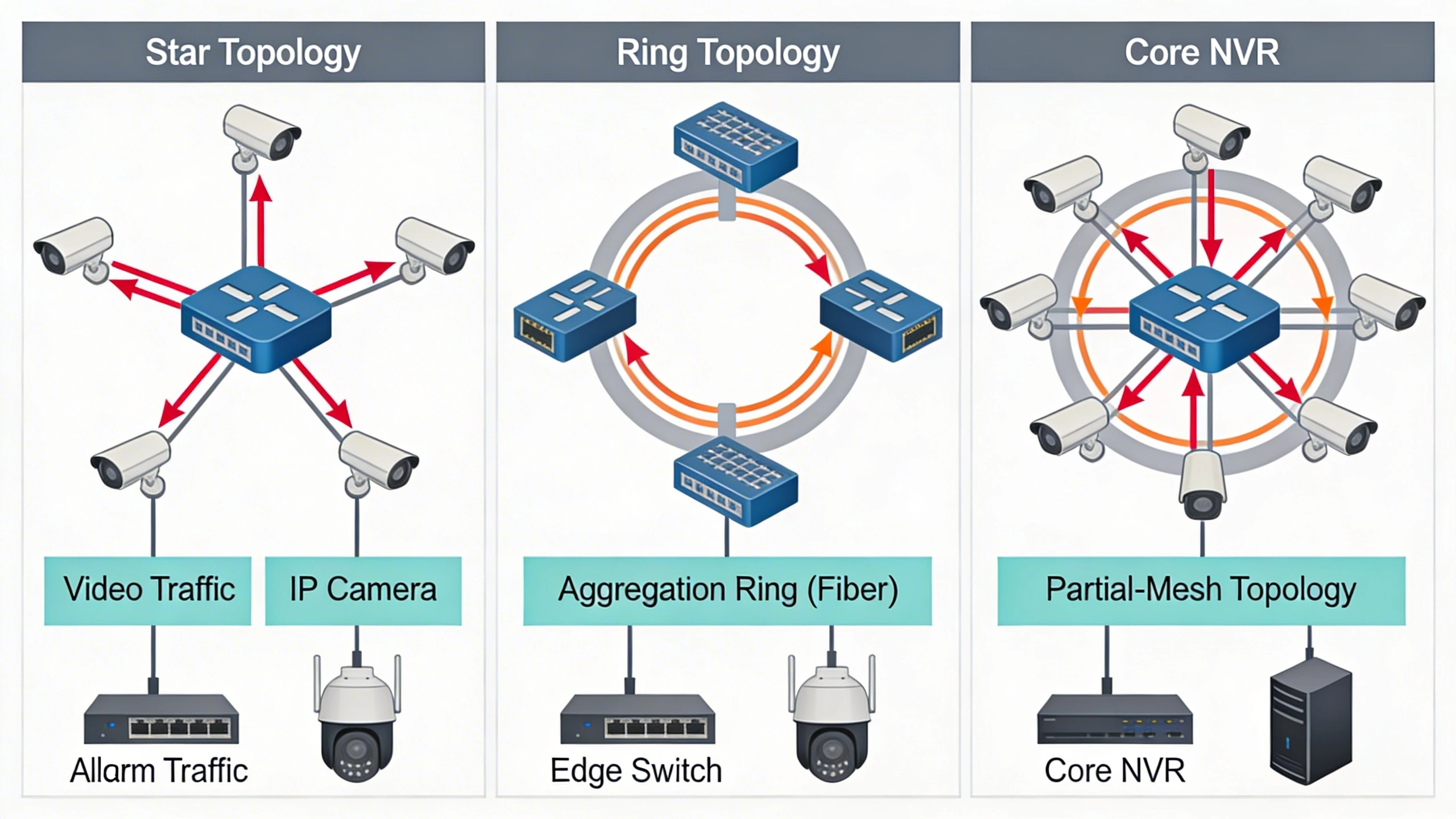
Prompt: Clean technical diagram comparing star, ring, and partial-mesh topologies for a security network with IP cameras connected to edge switches, aggregation rings via fiber, and core NVRs; include red failover arrows and labels for traffic types like video and alarms; industrial style, no people.
Alt Text: Comparison of security network redundancy topologies: star, ring, and mesh - Placement: After Core components and signal flow
Insert After: Core components and signal flow
Purpose: Illustrates the signal path and failover mechanisms, reinforcing the component explanations with a concrete flow diagram.
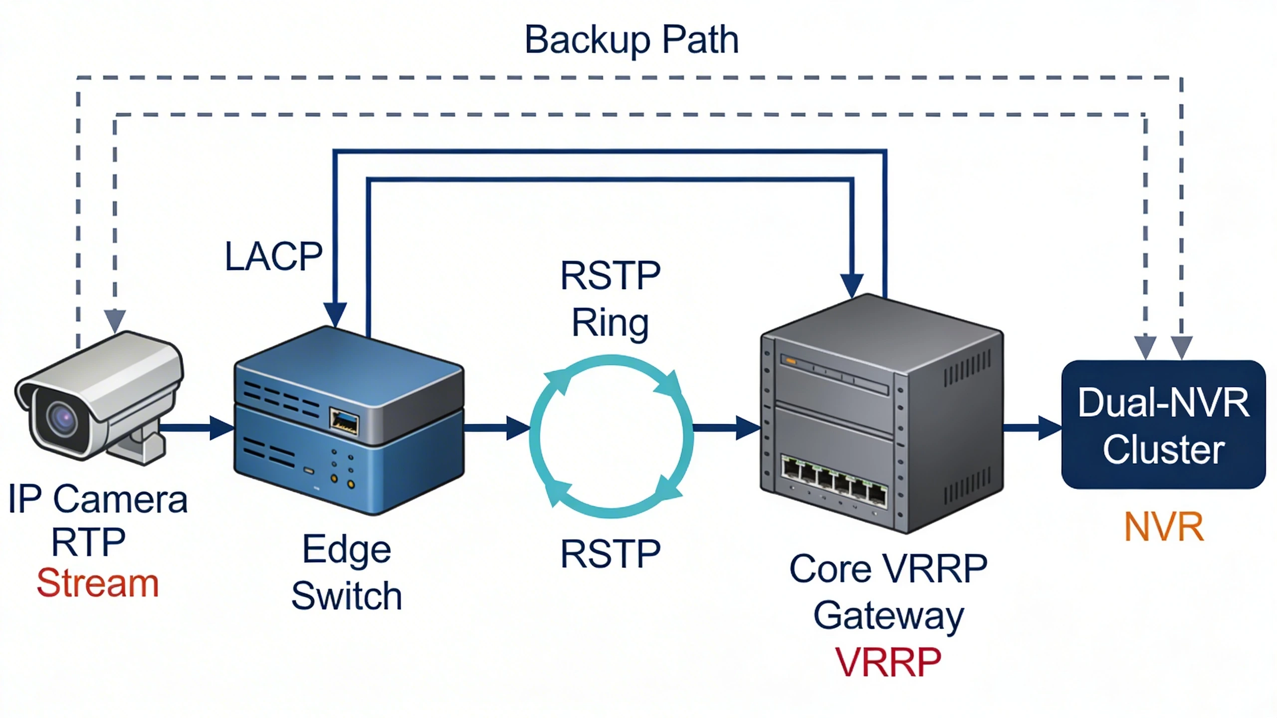
Prompt: Flowchart showing signal flow in a redundant security network: IP camera RTP stream over LACP to edge switch, RSTP ring to core VRRP gateway, then to dual-NVR cluster; dashed lines for backup paths, icons for components, labels for protocols and traffic priorities.
Alt Text: Signal flow diagram in redundant security network with failover paths - Placement: After Deployment and integration considerations
Insert After: Deployment and integration considerations
Purpose: Depicts a migration from single-path to redundant setup, aiding integrators in visualizing retrofit steps and tradeoffs.
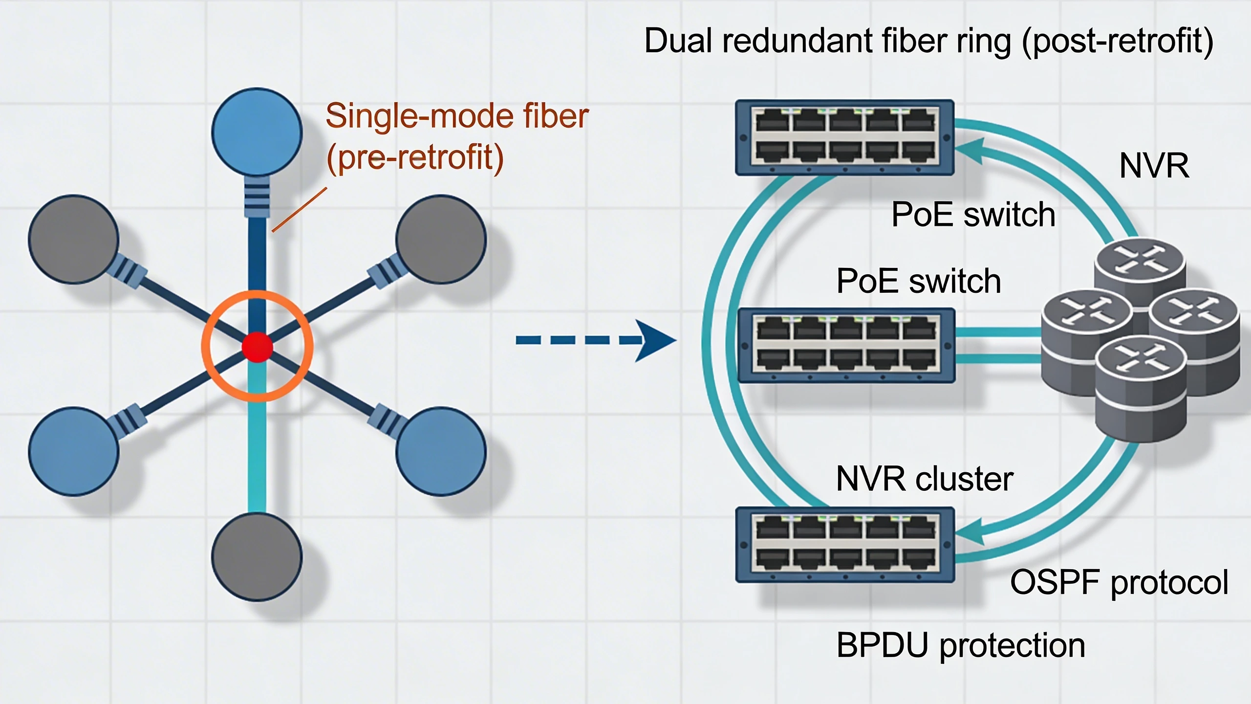
Prompt: Before-and-after migration diagram for campus security network upgrade: left side single fiber star topology with failure point highlighted, right side redundant fiber ring with PoE switches and NVR cluster; arrows showing change process, labels for cabling types and protocols added.
Alt Text: Migration diagram: upgrading campus security network from single path to redundant ring topology