When upgrading security at a remote utility substation, the perimeter intrusion detection system (PIDS) must stay online through extended blackouts or storms. Grid power flickers out too often in these locations, leaving fiber-optic sensors and PTZ cameras dark until diesel generators spool up. Teams often start with basic UPS units sized for a few hours, but discover they need layered redundancy—solar trickle-charging batteries alongside auto-start gensets—to match the 99.9% uptime SLAs demanded by critical infrastructure operators.
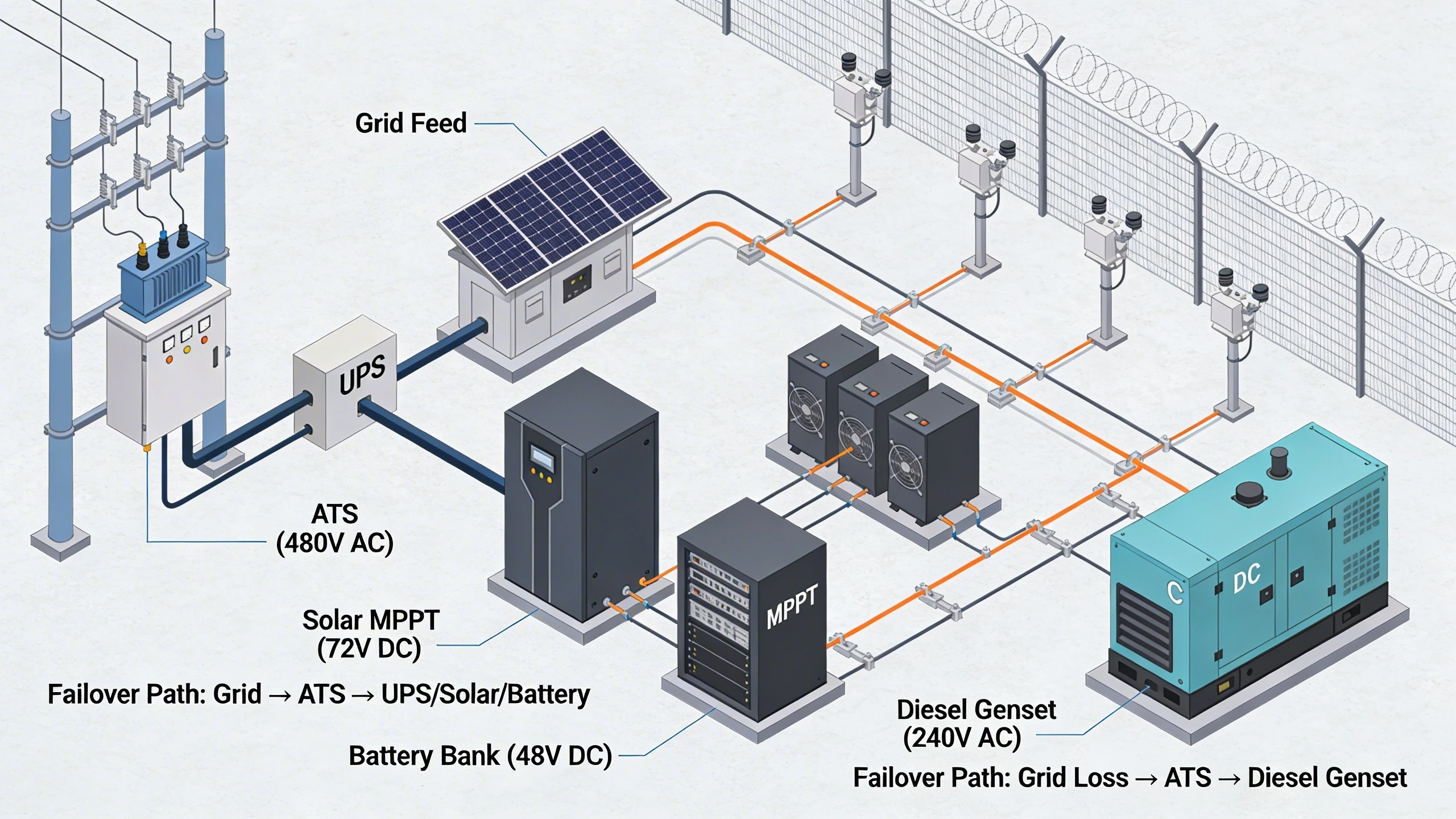
A hybrid approach typically emerges as the practical winner: primary grid feed with seamless UPS handover, augmented by renewables for shoulder seasons and a backup generator for deep outages. This balances capex against the operational risk of false-clear zones during power loss. For a 2km fence line with 50 sensors, expect to model load profiles from PoE draw (often 15-30W per device) and environmental derating, ensuring the design scales without overprovisioning conduit runs or trenching new feeds.
Retrofit projects on campuses or oilfield gates highlight why upfront power audits pay off. Skipping them leads to cascading failures, like battery drain pulling down adjacent IT closets. Instead, prioritize modular enclosures that house power gear near field devices, minimizing voltage drop over long cabling runs.
What the design decision looks like in practice
Picture a Midwest pipeline facility where winter storms knock out grid power for days. The security team deploys IR illuminators and microwave barriers along a 1.5km perimeter, but initial designs relied solely on rack-mounted UPS in the control room. Voltage sag over 500m Cat6 runs caused intermittent dropouts, triggering unnecessary alerts. Switching to distributed power nodes—each with IP67-rated batteries feeding local sensor clusters—eliminated those issues, while solar hoods on enclosures extended runtime without grid dependency.
In coastal campuses, salt air accelerates corrosion on standard panels, so engineers specify marine-grade enclosures with DC-coupled solar inverters. The decision tree starts with site surveys: calculate total watt-hours from device datasheets, factor in temperature de-rating (batteries lose 20-30% capacity below freezing), and simulate outage profiles from historical weather data. For multi-site rollouts, standardize on 48V DC distribution to leverage existing PoE++ switches, avoiding AC-DC conversions that introduce failure points.
Hands-on, this means staging power skids during low-traffic hours: bond grounds across zones, test failover scripting via dry contacts to the PSIM platform, and baseline consumption with a clamp meter before go-live. The payoff shows in post-incident logs—no more gaps during the 72-hour outage from Hurricane remnants.
System architecture and integration considerations
Core to any resilient design is segmenting power domains: edge devices on dedicated DC buses, separate from control room UPS. Integrate via Modbus or SNMP for real-time monitoring, feeding status into the overarching PSIM. For FortSense 4 deployments, this aligns with modular I/O cards that poll battery SOC and inverter faults without custom scripting. Avoid daisy-chaining sensors on single PoE injectors; use star topologies with managed switches supporting PoE pass-through and priority queuing during brownouts.
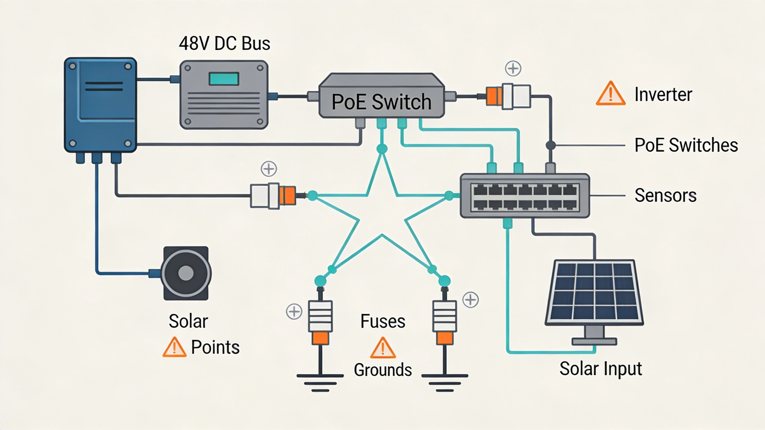
Layered redundancy demands careful fusing: primary grid to ATS (automatic transfer switch), paralleling UPS and solar MPPT controllers into a common bus. In practice, for a remote gatehouse, this might involve a 5kW Victron inverter stack with 10kWh LiFePO4 banks, auto-starting a 20kW genset on deep discharge. Cabling specs matter—use 10AWG for 48V runs under 100m to keep losses below 5%. Grounding loops from mixed AC/DC sources have sunk projects; mandate single-point bonds verified with a megohmmeter.
Scalability favors containerized microgrids: pre-fab enclosures with N+1 rectifiers, expandable bays for future EV charging tie-ins. This future-proofs against expanding sensor counts from added analytics cameras.
Operational workflows and field constraints
Field teams maintain these systems through weekly logs: visual checks on solar tilt angles (optimized biannually for latitude), electrolyte levels in wet-cell backups, and firmware updates on charge controllers. Dispatch workflows route via mobile apps pinging gateway telemetry, prioritizing hot-swap batteries over full skid swaps. In dusty aggregate sites, air filters on genset intakes extend service intervals, while rodent-proof conduit prevents chew-throughs common in rural zones.
Constraints like restricted access demand remote diagnostics: edge gateways with LTE failover report predictive alerts, like battery health trending down from cycle fatigue. Training emphasizes load-shed sequences—dropping non-critical lights before sensors—to stretch runtime. For integrator crews, this means carrying universal DC testers and torque wrenches for lug connections, ensuring compliance during annual audits.
Common failure points and design mistakes
Oversizing generators without soft-starters leads to nuisance trips on startup inrush from capacitive loads like camera domes. Underspec'd cabling exacerbates this, with IR drop starving endpoints during peak draw. Another pitfall: ignoring harmonic distortion from VFDs in nearby pumps, which degrades UPS performance—mitigate with active filters or K-rated transformers.
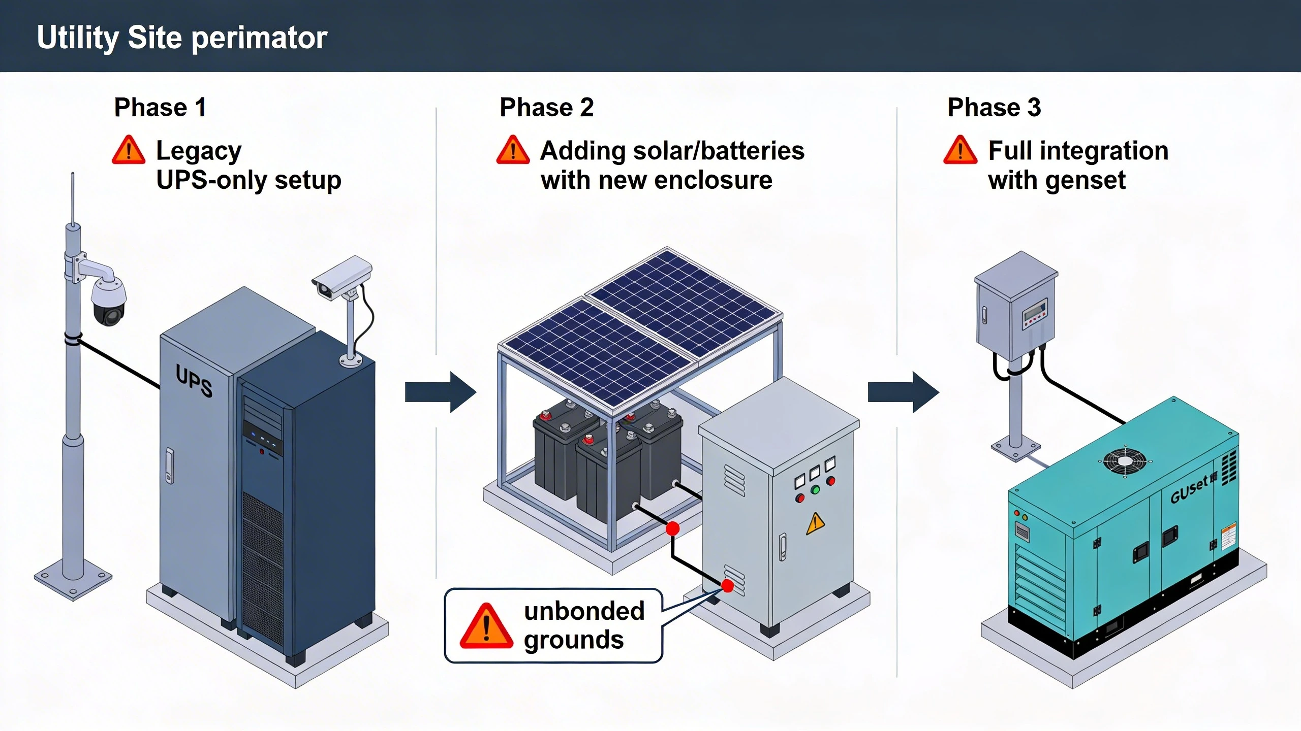
Forget to account for derating in enclosures? High ambients push components into thermal shutdown. Migration mistake: hot-swapping legacy 12V lead-acids for lithium without bus reconfiguration, causing polarity reversals. Always prototype on benches, simulating full load with resistors matched to sensor profiles.
What to verify before procurement
Request full load-test data from vendors, including step-response waveforms from 100% to 50% load. Confirm IP ratings and salt-fog certifications for enclosures, plus MTBF figures backed by field telemetry. Audit inverter efficiency curves across 20-100% loading—avoid units that tank below 90% at partial loads common in perimeters.
Check interoperability: Does the BMS integrate via standard OPC-UA or BACnet? Verify genset cold-start specs match local lows, and solar yield modeling tools output bankable reports. Finally, insist on 5-year spares availability and local service footprints to sidestep lead-time nightmares during surges.
Where to go next
Explore FortSense 4 for seamless power monitoring in PIDS setups. For tailored advice, request a design review. See applications in critical infrastructure security or North America deployments. Reference the Perimeter Intrusion Detection System glossary or PSIM glossary for terms.