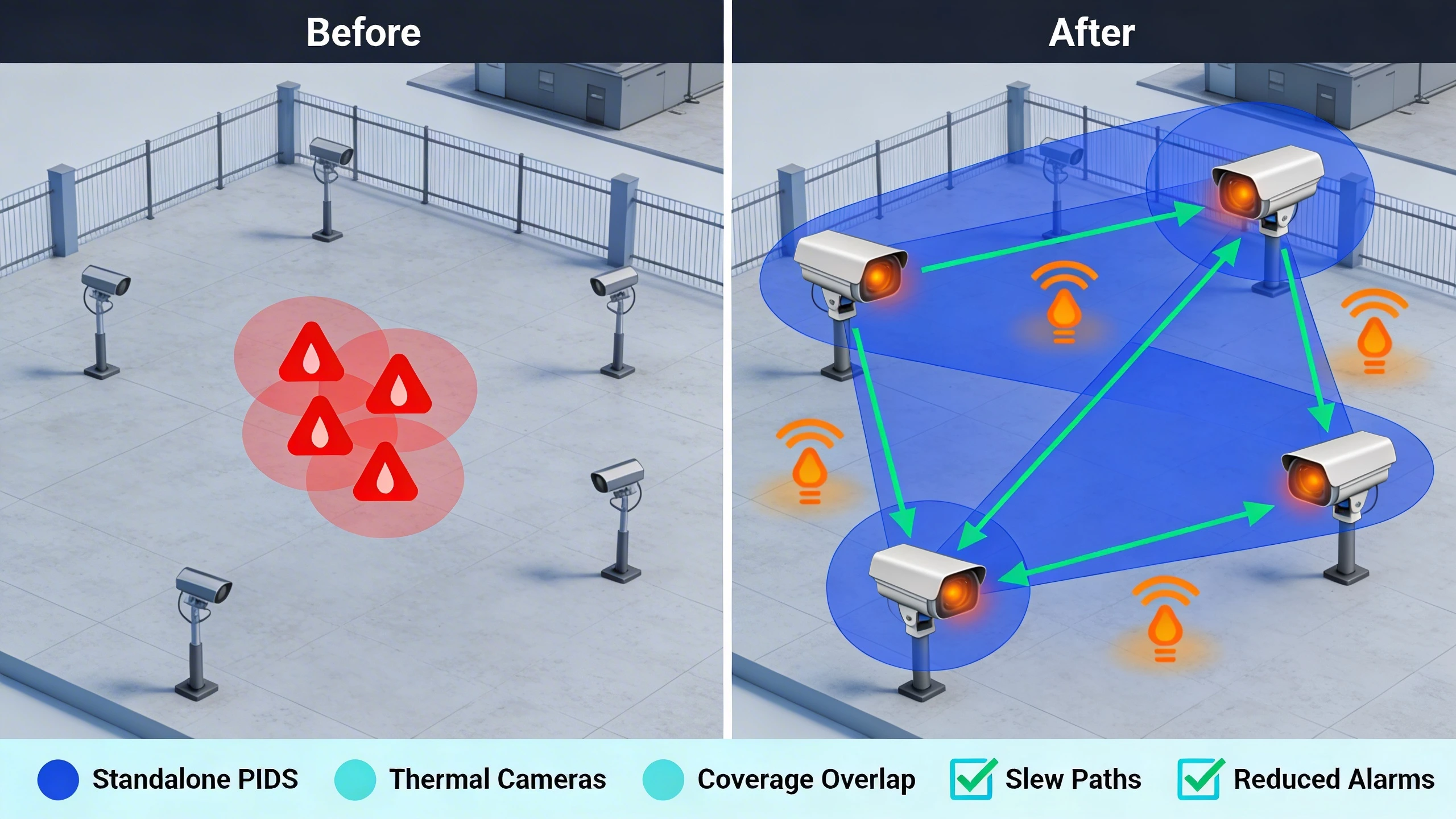
When retrofitting perimeter security at a utility substation spanning several acres, integrators often face the challenge of high false alarm rates from standalone Perimeter Intrusion Detection Systems (PIDS). These systems, typically relying on fence-mounted vibration sensors or buried fiber optics, excel at detecting physical intrusion attempts but struggle with environmental noise like wind, rain, or wildlife. Adding a layer of thermal imaging addresses this by providing rapid visual verification, allowing operators to distinguish genuine threats from benign events without constant human monitoring.
The decision to layer thermal cameras with PIDS fundamentally shifts the detection paradigm from alert flooding to targeted assessment. In practice, a PIDS sensor triggers on disturbance, immediately cueing a thermal PTZ camera to the precise location via preconfigured presets. This integration cuts nuisance alarms by enabling rule-based filtering—only verified human or vehicle intrusions escalate to response teams. For security managers at campuses or industrial sites, this approach not only improves detection confidence but also optimizes staffing by focusing attention where it matters.
Consider a multi-site energy provider upgrading legacy PIDS amid rising drone and insider threats. By overlaying thermal analytics, they achieve 24/7 coverage even in fog or total darkness, where visible cameras fail. The design tradeoffs involve balancing sensor density, network latency, and power redundancy, but the operational payoff is a more resilient perimeter that scales with threat evolution.
What the design decision looks like in practice
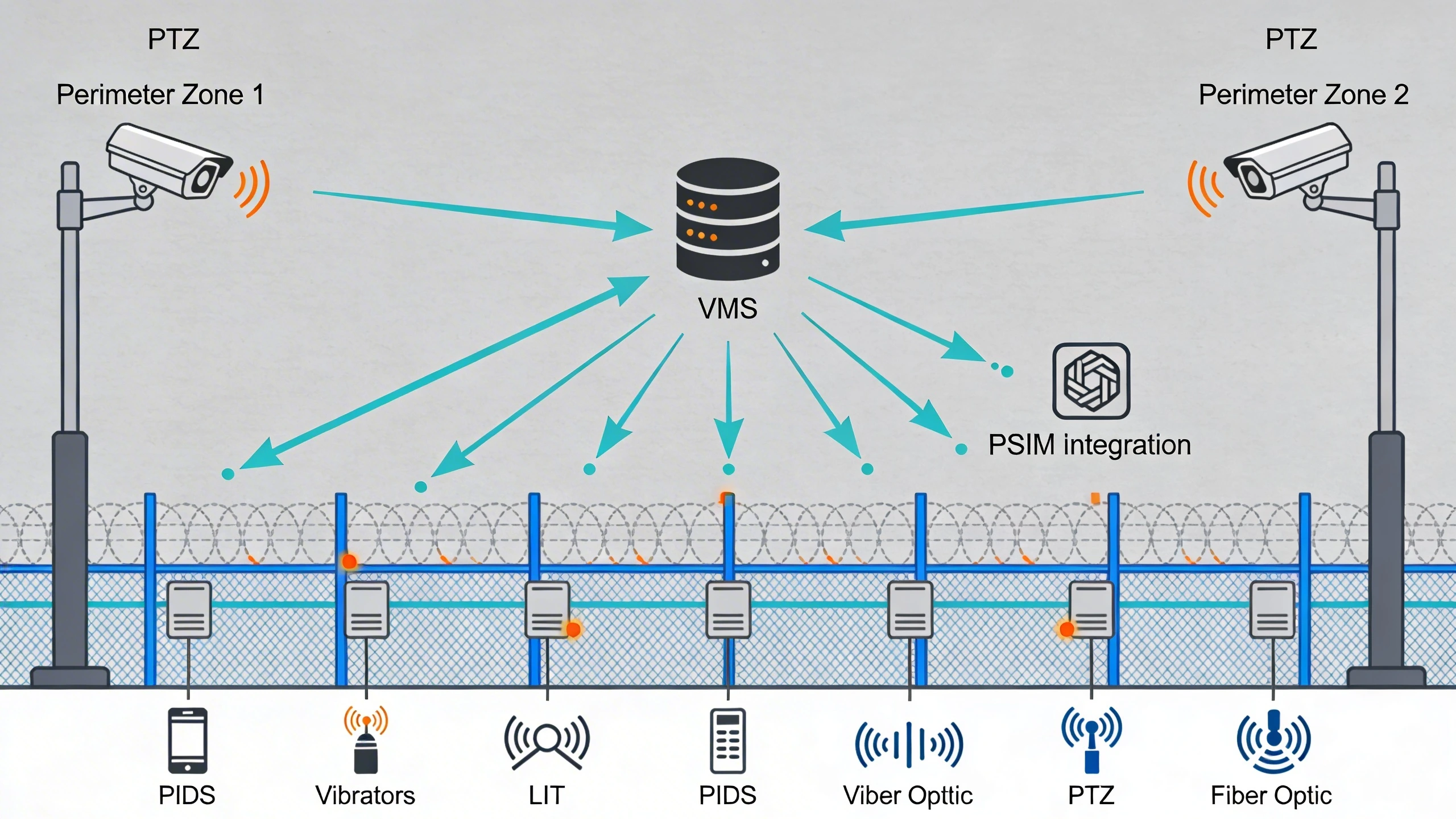
Implementing layered thermal and PIDS detection starts with mapping the perimeter's vulnerabilities. At a typical critical infrastructure fence line, PIDS sensors—such as coaxial strain gauges or infrared beams—form the primary detection layer, positioned to cover gates, walls, and approaches. When an alarm fires, the system logic directs networked thermal cameras to slew to GPS-coordinated presets, delivering a thermal snapshot or live stream for classification. This isn't merely additive; it's a sequential workflow where PIDS provides coarse location data, and thermal refines it with heat signature analysis.
In field deployments, this manifests as a central PSIM or VMS console displaying synchronized views: PIDS alarm zones highlighted alongside thermal video. Operators see a climbing intruder on the fence sensor trace, confirmed by a thermal image showing human form factor against cold background. For retrofit projects, existing PIDS wiring often reuses RS485 or IP gateways to trigger camera actions, minimizing cabling disruptions. The result is a detection loop that closes faster than manual patrols, critical for sites where response times dictate compliance.
Design variations emerge based on terrain. Flat utility yards might use fixed thermal cameras with wide FOV for overview, while hilly campuses deploy PTZ units for zoom verification. Success hinges on aligning field-of-view overlaps—PIDS zones must fall within thermal coverage to avoid blind spots.
System architecture and integration considerations
A robust architecture treats PIDS and thermal as interdependent nodes in a distributed system. PIDS controllers aggregate sensor data over hardened Ethernet or fiber, feeding into a head-end server that runs integration rules. Thermal cameras, often IP-based with onboard analytics, connect via PoE switches to the same backbone, enabling low-latency cueing under 2 seconds. Middleware like ONVIF-compliant VMS handles the handshaking, ensuring PIDS metadata (zone ID, alarm strength) populates thermal overlays.
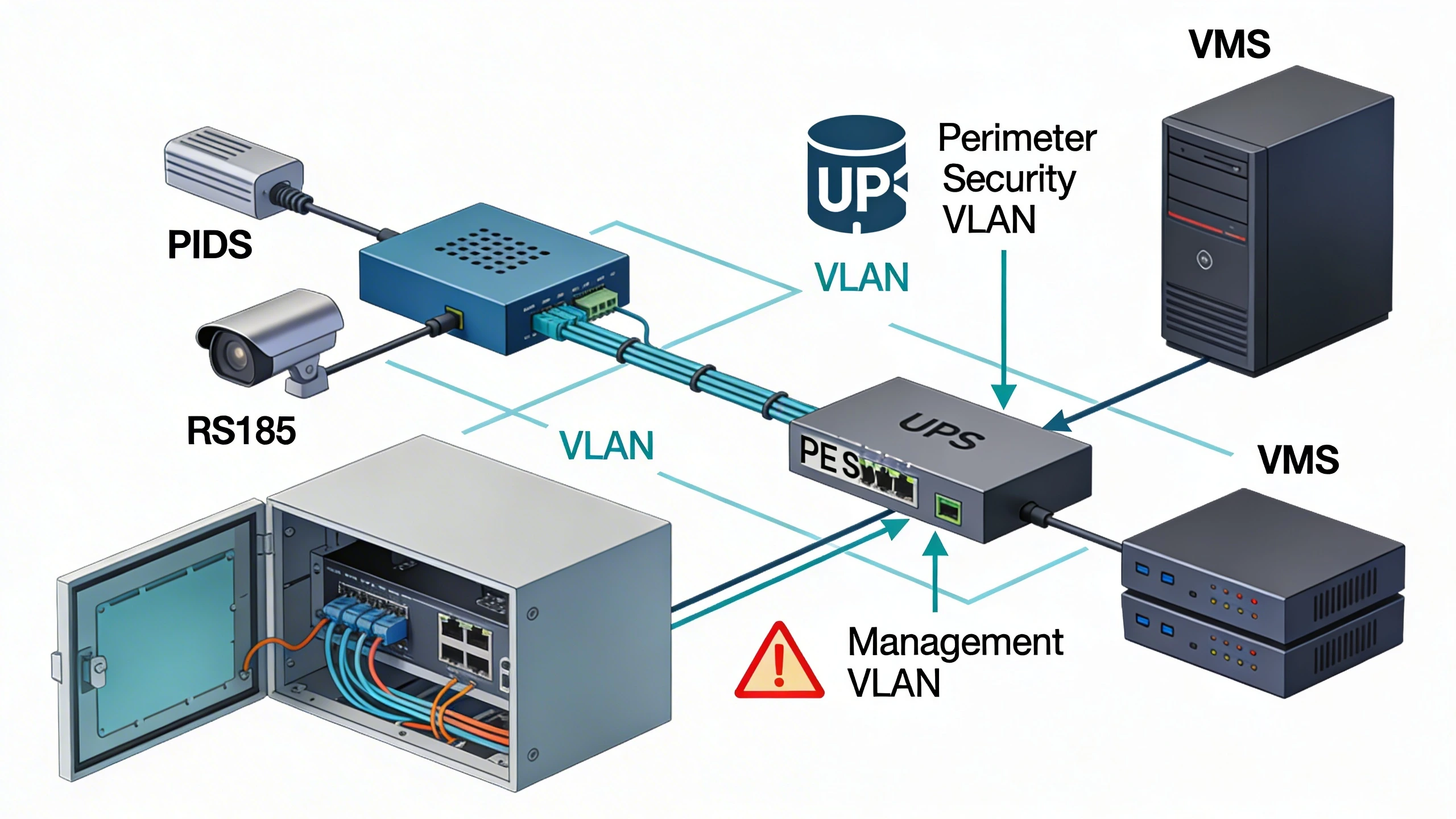
Integration challenges arise in legacy environments. Older PIDS may output dry contacts, requiring relay modules to mimic HTTP triggers for modern cameras. Network segmentation is non-negotiable—dedicated VLANs isolate sensors from IT traffic, with failover to cellular for remote sites. Power architecture demands UPS at enclosures and solar backups for off-grid perimeters, as thermal PTZ draw significant watts during slew. Scalability favors modular designs: start with 10 PIDS zones and 4 thermals, expand via software licenses.
Testing integration in staging reveals bandwidth needs; a 640x480 thermal stream at 15fps suffices for verification, but analytics demand higher res. Edge processing on cameras reduces server load, filtering basic motion before PIDS linkage.
Operational workflows and field constraints
Daily operations revolve around alarm triage. A night shift operator at a data center perimeter receives a PIDS alert on zone 7; the console auto-pops thermal video confirming an animal, auto-clearing the event. Escalated alarms trigger audio deterrents or guard dispatch with exact coordinates. Maintenance workflows include weekly sensor walks to recalibrate PIDS tension and thermal lens cleaning, logged via the PSIM for audit trails.
Field constraints shape workflows profoundly. Harsh climates demand IP67-rated enclosures with heaters for thermal lenses in sub-zero temps. Vegetation growth near fences can mask PIDS signals or thermal views, necessitating quarterly trims. For extended perimeters, wireless PIDS extenders bridge gaps, but latency spikes require thermal cueing timeouts. Training emphasizes hybrid verification—trust PIDS for detection, thermal for intent assessment.
Shift handovers benefit from event replay: review layered footage to contextualize unresolved alerts, reducing carryover fatigue.
Common failure points and design mistakes
One prevalent mistake is mismatched coverage: PIDS zones extending beyond thermal range leave alerts unverified, eroding trust. Designers overlook this by basing layouts on paper maps without LiDAR surveys, resulting in slew times exceeding 10 seconds. Another pitfall is over-reliance on analytics; thermal AI misclassifies in rain or heat haze, so always provision manual override paths.
Integration snags include firmware mismatches—PIDS v2.1 won't trigger ONVIF 2.6 cameras without patches. Power glitches during storms drop thermal slews, missing the verification window. Poor grounding causes EMI false PIDS triggers, cascading to unnecessary thermal activations and bandwidth clog. Migration errors involve phased cutovers without overlap, creating vulnerability gaps.
Avoid siloed deployments; unintegrated layers revert to standalone weaknesses. Regular drift testing—simulate climbs while monitoring cue accuracy—catches these early.
What to verify before procurement
Before committing, audit site specifics: measure fence lengths, elevation changes, and approach paths to spec sensor counts. Request vendor interop demos cueing sample PIDS to thermal via your VMS. Probe environmental resilience—does the thermal maintain detection in your worst fog? Review latency SLAs under load, simulating 20 simultaneous alarms.
Check expandability: modular enclosures? License-free scaling? Scrutinize support for hybrid networks, including fiber-to-Ethernet converters. Field-test nuisance rejection with local wildlife or wind data. Ensure PSIM maps support dynamic overlays for PIDS-thermal linkage. Finally, validate power budgets against your grid reliability.
Where to go next
Explore FortSense 4 for seamless PIDS-thermal integration tailored to critical sites. For critical infrastructure security insights, review our case studies. Ready for deployment? Request a design review or check North America deployments for regional expertise. Deepen understanding with the Perimeter Intrusion Detection System glossary and PSIM glossary.
For nuclear facilities, layered thermal and PIDS design should be mapped into the nuclear-facility PIDS design guide.