A fiber perimeter intrusion detection system works on welded mesh only when the rigid panels, posts, clamps, sensing cable, processor configuration, and alarm-verification workflow are engineered as one system. The design must preserve useful vibration transfer while controlling discontinuities at seams, repairs, posts, gates, corners, and toppings.
Welded mesh can transmit intrusion-generated vibration effectively, but rigidity alone does not guarantee detection. The selected product must support the actual fence configuration, and the finished installation must be validated on representative panels. There is no universal attachment spacing, cable height, number of passes, tension value, or sensitivity setting for every welded-mesh perimeter.
Why Welded Mesh Behaves Differently From Chain-Link
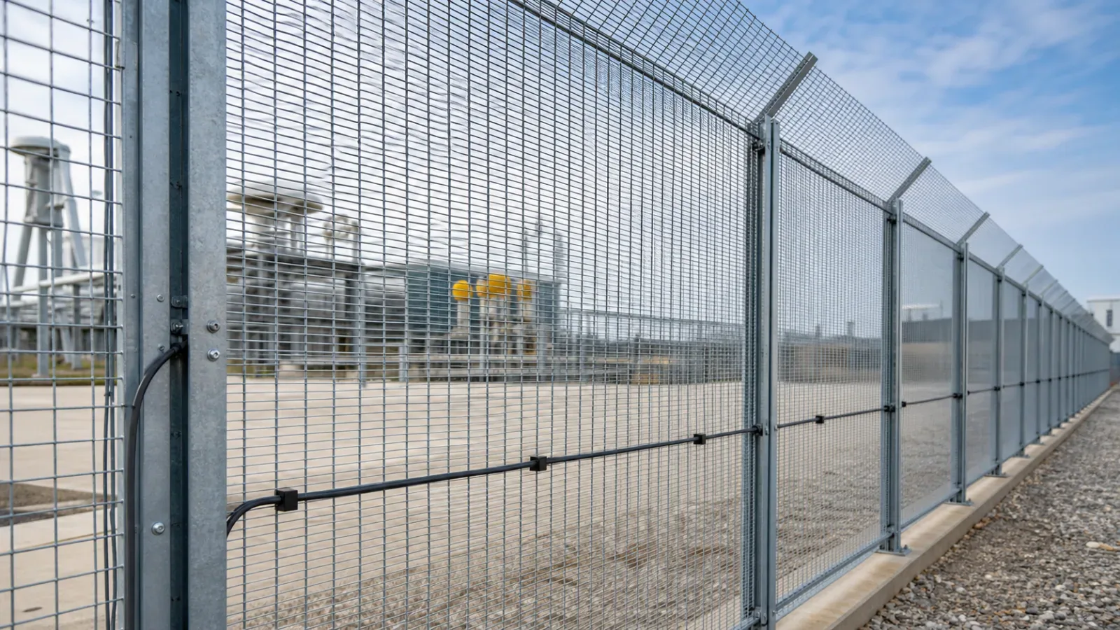
Chain-link fabric flexes and oscillates across a relatively broad area. Welded mesh is a sequence of rigid panels connected through posts, rails, clamps, brackets, and foundations. Those interfaces determine how attack energy reaches a fence-mounted sensing cable.
The NPSA barrier-mounted PIDS guidance states that each technology has barrier-specific requirements. A barrier that is too rigid may not transfer sufficient vibration, while one that is too flexible can increase environmental alarms. NPSA identifies metal weld mesh as capable of transmitting vibration to sensor-cable PIDS, but that does not make every welded-mesh construction equivalent.
A panel can respond consistently within its own frame while a loose clamp amplifies vibration or a rigid post attenuates it before the next panel. Treat the perimeter as connected mechanical sections, not one uniform sensing surface. For flexible fabric, use the separate chain-link fiber PIDS attachment guide.
Start With the Host Fence, Not the Sensor Settings
Survey the fence before freezing a cable path. Record the panel manufacturer, mesh aperture, wire diameter, reinforcement folds, height, post type, foundations, rails, clips, clamps, fasteners, coatings, repairs, toppings, and nearby environmental sources.
Identify loose, bent, corroded, damaged, or replacement panels and mark every change in construction.
Check post alignment, foundations, base plates, brackets, rails, and panel-to-post connections.
Remove vegetation contact and document signs, conduit, lighting cables, or other fence attachments.
Map roads, machinery, drainage, public contact, wind exposure, wildlife routes, and maintenance activity.
Separate gates, corners, wall returns, height changes, and toppings into explicit transition details.
A processor cannot reliably compensate for an unstable barrier. Loose brackets, moving signs, unsecured conduit, or vegetation can become repeatable nuisance sources. An unusually rigid repair can create the opposite problem by reducing the vibration that reaches the sensor. Use the survey to define the architecture, then create the component schedule with the fiber PIDS retrofit bill of materials.
Design the Sensing Route Around Mechanical Continuity
Keep the sensing cable in effective mechanical contact with the intended fence element while protecting it from crushing, abrasion, excessive local pressure, sharp bends, water traps, and unauthorized access. Follow the current manufacturer design for the exact cable, processor, fence construction, and product revision.
Horizontal Versus Vertical Attachment
Some systems use horizontal runs; others use vertical, serpentine, or product-specific patterns. Choose the orientation by required attack detection, tested vibration propagation, panel profile, post crossings, processor behavior, and manufacturer support, not by installer convenience.
Define which climb, cut, lift, penetration, and tamper events the operational requirement expects to detect.
Confirm how the proposed route crosses reinforcement folds, seams, posts, and replacement panels.
Verify that the orientation and attachment method are supported for the selected system.
Prove the route on a representative trial section before repeating it across the perimeter.
Manufacturer examples are useful only within their named products. Senstar describes a welded-wire integration example and publishes separate FiberPatrol FP400 integrator resources. These materials demonstrate why layout and installation instructions are product-specific; they are not universal fiber PIDS specifications.
Maintain Coupling Without Damaging the Cable
A cable hanging away from the mesh may receive inconsistent vibration. A fastener that crushes, pinches, bends, or abrades the cable can damage it or change its response. Inspect contact and protection at every attachment, panel fold, bracket, seam, and post.
Use the approved fastener type, orientation, installation tool, and environmental rating.
Keep the cable supported without unsupported spans or excessive localized load.
Maintain the specified bend radius and protect post crossings from sharp hardware.
Avoid contact with cut mesh, damaged coatings, clamps, burrs, and dissimilar-metal edges.
Keep protective sleeves or channels from isolating the sensor from the vibration it must measure.
Coordinate optical and mechanical continuity through the fiber-optic PIDS cable-route design process.
Treat Posts and Panel Seams as Test Locations
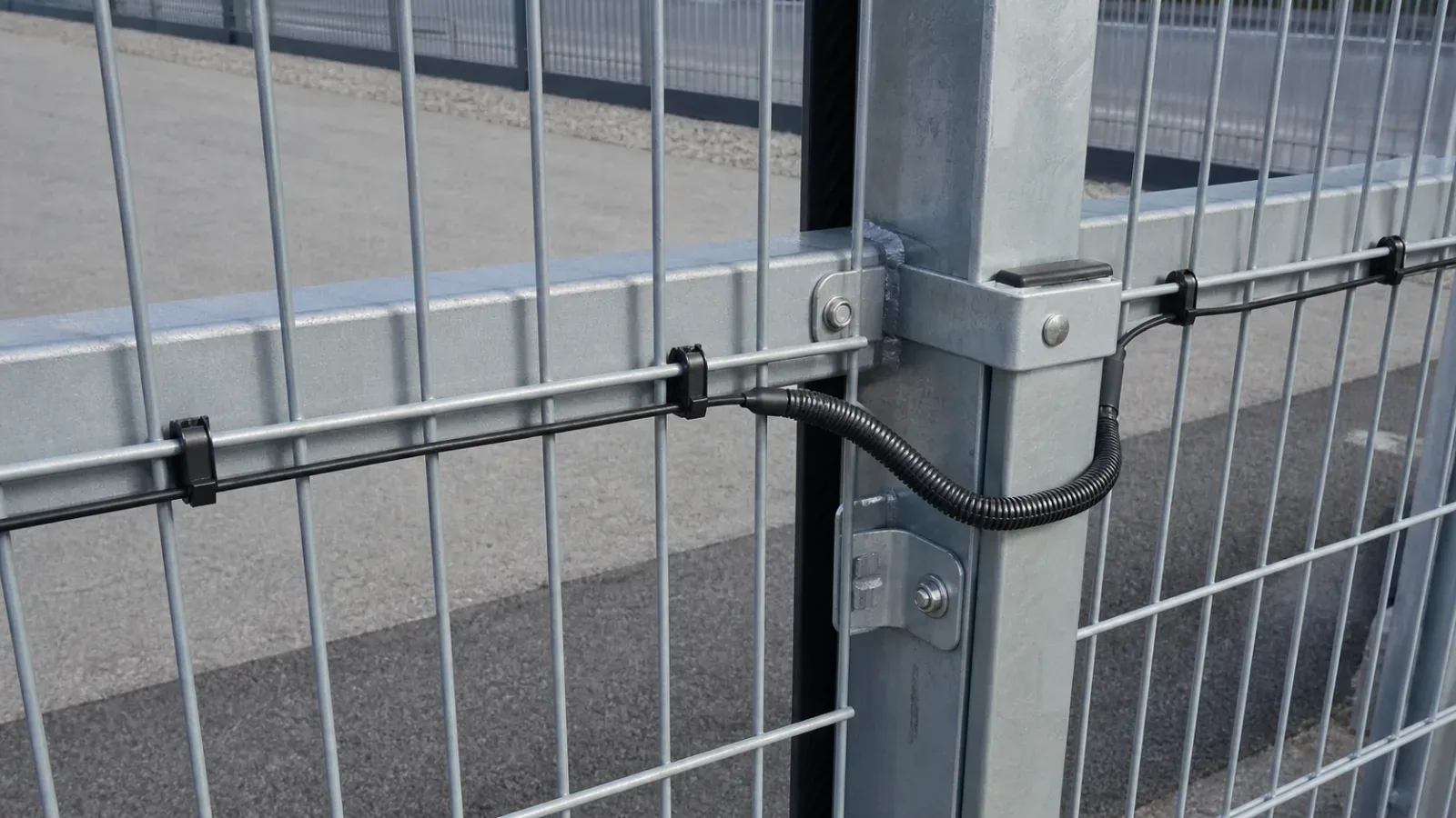
Posts and seams are not details to hide inside an average sensitivity setting. A panel-to-post interface may transfer vibration well, attenuate it, amplify it through loose hardware, or create a mechanically quiet section around a rigid foundation.
Map where the cable crosses each interface. During commissioning, test panel centers, both sides of representative posts, seams, original-to-replacement boundaries, and repaired sections. If performance changes materially, investigate the route and mechanical condition before raising zone sensitivity. Increasing sensitivity across an entire zone to compensate for one weak seam can create nuisance alarms on better-coupled panels.
Account for Anti-Climb Apertures, Profiles, and Coatings
Small-aperture anti-climb mesh changes available attachment space and may include reinforcement folds that interrupt cable contact. Confirm that fasteners fit without spreading the mesh, that the route follows the intended structural wire, and that protection does not create a foothold or handling point. Keep attachments inspectable from the secure side.
Galvanized and powder-coated fences also require corrosion control. Review exposed steel, coating damage beneath overtightened hardware, incompatible metals, water-retaining sleeves, ultraviolet degradation, and sharp edges near cable crossings. A repair that changes panel stiffness must be recorded and retested.
NPSA recommends secure-side installation for barrier-mounted PIDS and emphasizes that detection should be combined with physical delay, alarm verification, and response. The PIDS is not a replacement for the fence or the control-room workflow.
Use Controlled Handoffs at Gates, Corners, and Toppings
End the standard straight-panel detail at a defined handoff before sliding or swing gates, corners, changes in height, wall interfaces, and flexible toppings. These features have different motion, abrasion, access, protection, and verification requirements.
Mark the final standard panel and the start and end of every transition.
Show cable protection, service loops, enclosures, bypasses, and any differently sensed section.
Assign the alarm zone and verification camera responsible for the transition.
Define a transition-specific acceptance test instead of extending the straight-panel assumption.
Welded-Mesh Installation Decision Matrix
Uniform panels with secure clamps: use a repeatable standard detail, then validate representative panel centers, seams, and posts.
Loose clips, rails, or brackets: repair before baselining; repeat nuisance and attack tests after the mechanical correction.
Mixed original and replacement panels: treat each construction as a separate condition and test both sides of every transition.
Deep reinforcement folds: validate an approved route that maintains effective contact across the profile.
Corrosion or coating damage: repair the barrier and remove abrasion risks before attaching the sensing cable.
Routine public contact or vegetation: improve clearance and test normal activity as part of the nuisance baseline.
Gates, corners, toppings, or height changes: create a separate engineered handoff and acceptance case.
No representative test section: hold full deployment and run the fiber PIDS proof-of-concept plan.
Configure the Processor for the Installed Fence
Build the initial baseline only after the panels, clips, attachments, vegetation clearance, and transition details are complete. Observe representative weather and nearby site activity, then tune the processor through the manufacturer-supported workflow and the site operational requirement.
NPSA frames commissioning as a balance between detection and unwanted alarms, with alarms normally verified through video or another control-room process. If acceptable behavior requires extreme settings, revisit fence condition, cable coupling, zone boundaries, and technology fit. Use the DAS no-fit decision framework when the barrier, environment, or response model remains unsuitable.
Commissioning Checklist
Confirm the installed panels, posts, rails, foundations, repairs, and transitions match the approved survey.
Verify the sensing route and attachment hardware follow the approved manufacturer design.
Inspect cable contact, support, bends, fasteners, coating condition, and sharp-edge clearance.
Photograph representative panels, seams, posts, repair boundaries, and transition handoffs.
Test approved intrusion simulations at panel centers and on both sides of representative interfaces.
Test sections near roads, machinery, vegetation, drainage, wildlife, and normal human activity.
Confirm each alarm identifies the correct zone and reaches the monitoring and response workflow once.
Verify cameras provide usable views for every tested alarm area.
Record settings, weather, method, detection result, nuisance observations, and corrective action.
Correct mechanical defects before compensating through sensitivity changes, then retest modified sections.
The NPSA PIDS evaluation schemes reinforce that evaluation applies to defined products and deployment configurations. A visually tidy cable route is not accepted until the installed system proves detection, nuisance behavior, localization, verification, resilience, and maintainability.
Implementation Note
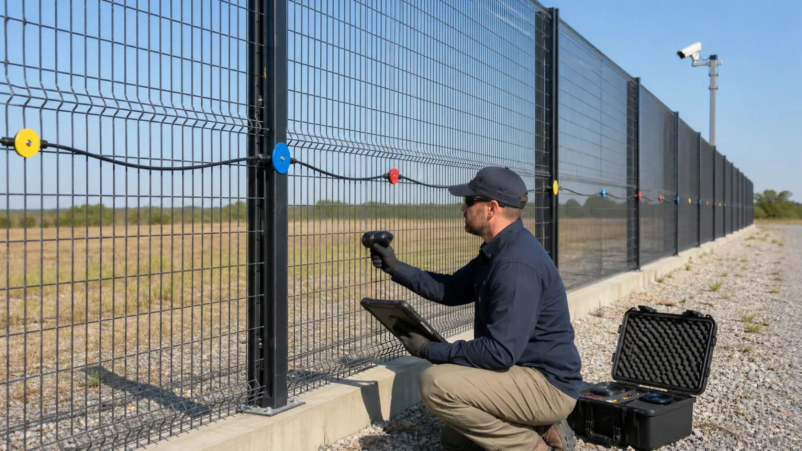
Freeze the accepted welded-mesh detail as a controlled drawing only after representative commissioning passes. Record the fence type, sensor model, route orientation, attachment hardware, protected crossings, transition handoffs, zone mapping, configuration reference, and acceptance tests.
Any panel replacement, post repair, topping modification, or cable reroute should trigger inspection and bounded recommissioning. A repaired section may look equivalent while transmitting vibration differently.
Source and Design Controls
Barrier compatibility and welded-mesh vibration transfer: NPSA barrier-mounted PIDS guidance.
Secure-side installation, verification, and layered security: NPSA Guide to Perimeter Intrusion Detection Systems.
Configuration-specific product evaluation: NPSA PIDS evaluation schemes.
Product-specific welded-wire and fiber installation examples: Senstar fence-sensor resources; these are manufacturer examples, not general requirements.
Request a Welded-Mesh Design Review
For high-consequence sites, connect the installation record to the wider critical-infrastructure perimeter design, the United States deployment context, and the control-room verification process. Review how FortSense 4 maps physical sensor zones into alarm workflows, then request a project review for the fence layout, sensing route, zones, integration points, and commissioning evidence.