A fiber optic fence sensor bill of materials cannot be calculated from fence length alone. A defensible BOM starts with a surveyed route and selected topology, then accounts for sensing cable, non-sensing lead cable, service loops, attachment hardware, gates, transitions, splices, enclosures, controller equipment, power, networking, integration, testing, labeling, documentation, and approved spares.
The controlling procurement rule is simple: every quantity must trace to a drawing, measured route, topology decision, manufacturer instruction, integration requirement, or acceptance deliverable. Generic allowances cannot replace site-specific engineering.
NPSA perimeter intrusion detection guidance places the operational requirement before specification, tender, installation, commissioning, and handover. It also identifies barrier condition, environment, access, integration, power, response, and local surroundings as selection and specification inputs. Those are BOM inputs, not details to resolve after purchasing.
What Goes in a Fiber PIDS Retrofit BOM?
Approved design, survey, zone, and cable-route documents.
Sensing cable, non-sensing lead cable, and approved service or isolation loops.
Fence attachments plus cable protection at posts, corners, gates, and exposed transitions.
Splice closures, trays, sleeves, pigtails, connectors, glands, and outdoor enclosures.
Controller or interrogator, cabinet, power, circuit protection, and backup power.
Network, relay, VMS, PSIM, alarm-panel, and time-synchronization interfaces.
Installation, cleaning, inspection, labeling, and optical test materials.
Repair materials, approved spares, configuration records, as-builts, and handover evidence.
Not every project needs every conditional component. Loop topology, redundant paths, remote cabinets, gate bypasses, licensed interfaces, communication converters, and supplementary gate sensors depend on the selected system and site.
Use the fiber-optic fence sensor buyer guide when the sensing technology or vendor class is still being selected. This BOM method begins after the operational requirement and candidate architecture are defined.
Start With Survey Inputs, Not a Parts Catalog
Divide the perimeter into homogeneous survey segments. A new segment begins whenever fence construction, height, condition, cable route, zone function, gate arrangement, environmental exposure, or installation method changes.
Measured protected length by fence type and route.
Fence height, fabric, posts, rails, toppings, rigidity, damage, and repair needs.
Corners, elevation changes, wall interfaces, culverts, buildings, and penetrations.
Swing gates, sliding gates, emergency exits, maintenance openings, and vehicle lanes.
Proposed controller, cabinet, power, network, and splice-enclosure locations.
Required alarm zones, camera views, response areas, and control-room interfaces.
Exposure to salt, UV, moisture, flooding, chemicals, vegetation, wildlife, and vandalism.
Installation access, working restrictions, outage windows, and maintenance strategy.
A current FiberPatrol planning and installation guide illustrates why this survey matters: its product-specific planning process derives configuration and installation requirements from fence type, condition, length, zones, sensor and lead routes, gates, nearby structures, roads, vegetation, and electronic-equipment locations. The exact hardware rules remain vendor-specific, but the takeoff discipline is broadly applicable.
Use the FortSense fiber optic PIDS cable-route design guide before freezing quantities. The approved route should drive the BOM; cable quantities should not make routing decisions by accident.
Build a Mandatory and Conditional Procurement Matrix
Resolve every line as mandatory, conditional, excluded, or owner-furnished before tender. An undefined provisional item simply moves uncertainty into a later change order.
Design package - mandatory: controlled perimeter drawing, route chainage, zones, gates, cabinets, splice points, topology, and revision status.
Head end - mandatory: selected controller or interrogator, channels, firmware, licenses, environmental limits, and interfaces.
Sensing cable - mandatory: approved cable construction, fiber compatibility, drum plan, detecting route, loops, tails, and vendor approval.
Lead cable - conditional: measured head-end route, protection, fiber type, topology, termination, and splice method.
Mounting and protection - mandatory or conditional: approved attachments, tools, conduit, sleeves, guards, strain relief, and transition protection.
Gates and transitions - conditional: gate loops, bypass cable, flexible protection, enclosures, auxiliary inputs, or supplementary detection.
Splicing and termination - conditional: closures, trays, sleeves, organizers, pigtails, connectors, adapters, patch cords, and inspection requirements.
Cabinet, power, and network - project-defined: rack or field enclosure, thermal and ingress controls, PSU, UPS, protection, switch ports, and transceivers.
Alarm integration - project-defined: relay or IP modules, protocol licenses, event mapping, supervision, camera association, and failure behavior.
Testing and handover - mandatory: cleaning, inspection, optical tests, commissioning evidence, labels, configurations, manuals, training, and as-builts.
The NPSA FiberPatrol 1150 listing provides a useful example of a product-level evaluated configuration that identifies specific processors, sensing cables, software, and enclosure kits. A component should not be substituted only because its generic optical description appears similar.
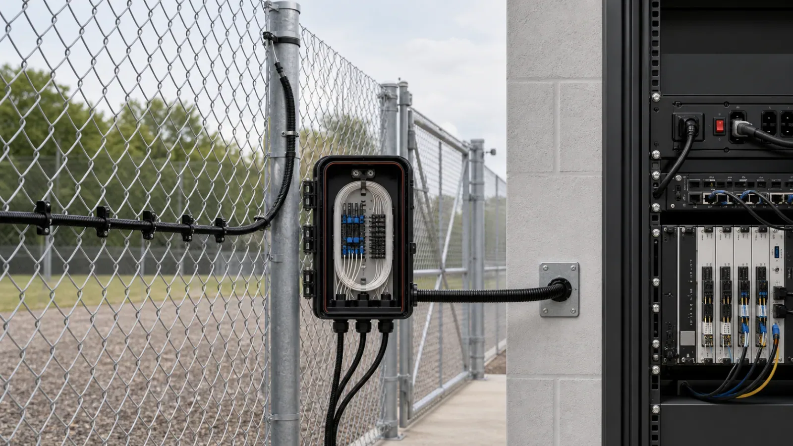
Calculate Sensing Cable From the Installed Route
Divide the route into segments i = 1 through n. For each segment, Li is measured segment length and pi is the approved number of sensing-cable passes. The base detecting route is Ri = Li multiplied by pi. Add each gate allocation Gj, manufacturer-required service or isolation loop Sk, termination or enclosure tail Tm, and a documented project contingency Cr.
The takeoff is: Qsensor = sum(Ri) + sum(Gj) + sum(Sk) + sum(Tm) + Cr. This is an engineering framework, not a standard formula or universal allowance. Define Cr from drum sizes, survey uncertainty, repair strategy, site access, installation method, and the consequence of a short reel.
Calculate non-sensing lead cable separately: Qlead = measured head-end route + approved lead service loops + termination tails. Product topology determines whether one or more lead cables, return paths, start/end modules, or splice arrangements are required.
Once quantities are established, use the fiber PIDS lifecycle cost model to evaluate economic consequences. This BOM page owns what must be purchased; the TCO page owns lifecycle cost and risk.
Calculate Attachment Hardware Without Inventing Spacing
For each segment, si is the attachment spacing prescribed by the selected manufacturer for that fence and cable, while Hi represents additional attachment points at posts, corners, loops, gates, and protected transitions. The preliminary takeoff is Qattach = sum(ceiling(Ri divided by si)) + sum(Hi).
The formula does not establish si, attachment material, tension, placement height, or reinforcement. Those values must come from current product instructions and any approved field trial. The Senstar FP400 product page provides one product-specific example using UV-resistant cable ties; another product or environment may require different material, geometry, tools, or locking methods.
Manufacturer-approved attachment type and dimensions.
Corrosion, UV, temperature, chemical, and environmental suitability.
Required installation or tensioning tool.
Approved locking, inspection, and replacement method.
Separate hardware for posts, corners, loops, gates, walls, conduit, and vulnerable details.
Treat Gates and Transitions as Individual Assemblies
Do not hide gates inside the linear cable allowance. Give every opening its own assembly row with gate type, clear width, movement envelope, sensing method, bypass or loop arrangement, strain relief, protection, splice or enclosure need, gate-position input, zone, and camera-verification mapping.
Manufacturer methods can differ materially by gate type. The cited FiberPatrol guide, for example, describes product-specific sensing arrangements for supported swing gates and different treatment for sliding gates. Use that only as an example of why the selected manufacturer method must control the BOM.
Corners, fence-height changes, wall transitions, road crossings, building penetrations, and sensing-to-lead transitions need the same assembly-level treatment. Detailed mounting spacing, tension, and gate installation remain in their dedicated installation specifications.
Build the Splice and Enclosure Schedule
Every planned splice should appear in a controlled schedule before procurement. Record fibers entering and leaving, function, splice count, tray capacity, closure type, cable entries, glands, mounting, environmental exposure, service-loop storage, tamper requirement, and drawing reference. Derive sleeves, trays, organizers, closures, glands, brackets, and consumables from that schedule.
Avoid unnecessary splices, but do not remove a serviceable transition merely to advertise a lower component count. Maintainability, route access, repair time, topology, optical performance, and security exposure are engineering tradeoffs. If existing strands are proposed, first assess dark fiber for perimeter DAS reuse.
Include Power, Network, and Alarm Integration
A passive sensing cable does not eliminate head-end infrastructure. Account for the controller, power supply, breakers or circuit protection, backup power, enclosure, network path, relays or IP interfaces, monitoring licenses, time synchronization, and configuration backup.
Alarm, tamper, communication, health, and degraded-state events.
Physical zone names and camera associations.
Relay state, message format, acknowledgement, and supervision.
Network ports, reach, cybersecurity controls, and redundancy.
Power load, backup autonomy, failure behavior, and recovery.
VMS, PSIM, alarm-panel, or control-room licensing and test requirements.
Review FortSense 4 when the architecture requires passive fiber detection with physical zones plus relay or IP integration into the site alarm workflow.
Avoid Procurement Traps That Cause Change Orders
Using fence length as cable quantity: this omits multiple passes, gates, lead routes, service loops, tails, and topology returns.
Ordering before topology is frozen: line, loop, split, redundant, and return arrangements change cable and splice quantities.
Specifying generic cable ties: material, dimensions, locking method, compatibility, and tools remain undefined.
Ignoring drum planning: total length can be adequate while reel lengths force an unplanned splice or unusable remainder.
Treating gates as ordinary panels: movement, protection, bypass, loops, auxiliary inputs, and alternate detection add separate assemblies.
Omitting licenses and interface modules: the hardware can arrive without the required alarm or video workflow.
Leaving optical test materials out of scope: the contractor may be unable to produce contract-compliant inspection and test evidence.
Applying a universal spare percentage: spares should follow repair method, packaging, lead time, access, and replaceable-unit analysis.
Accepting quantities without drawing references: untraceable items cannot be reconciled during installation or change control.
Evaluate range and channel assumptions separately with the DAS detection-range evaluation framework. A BOM cannot validate a performance claim.
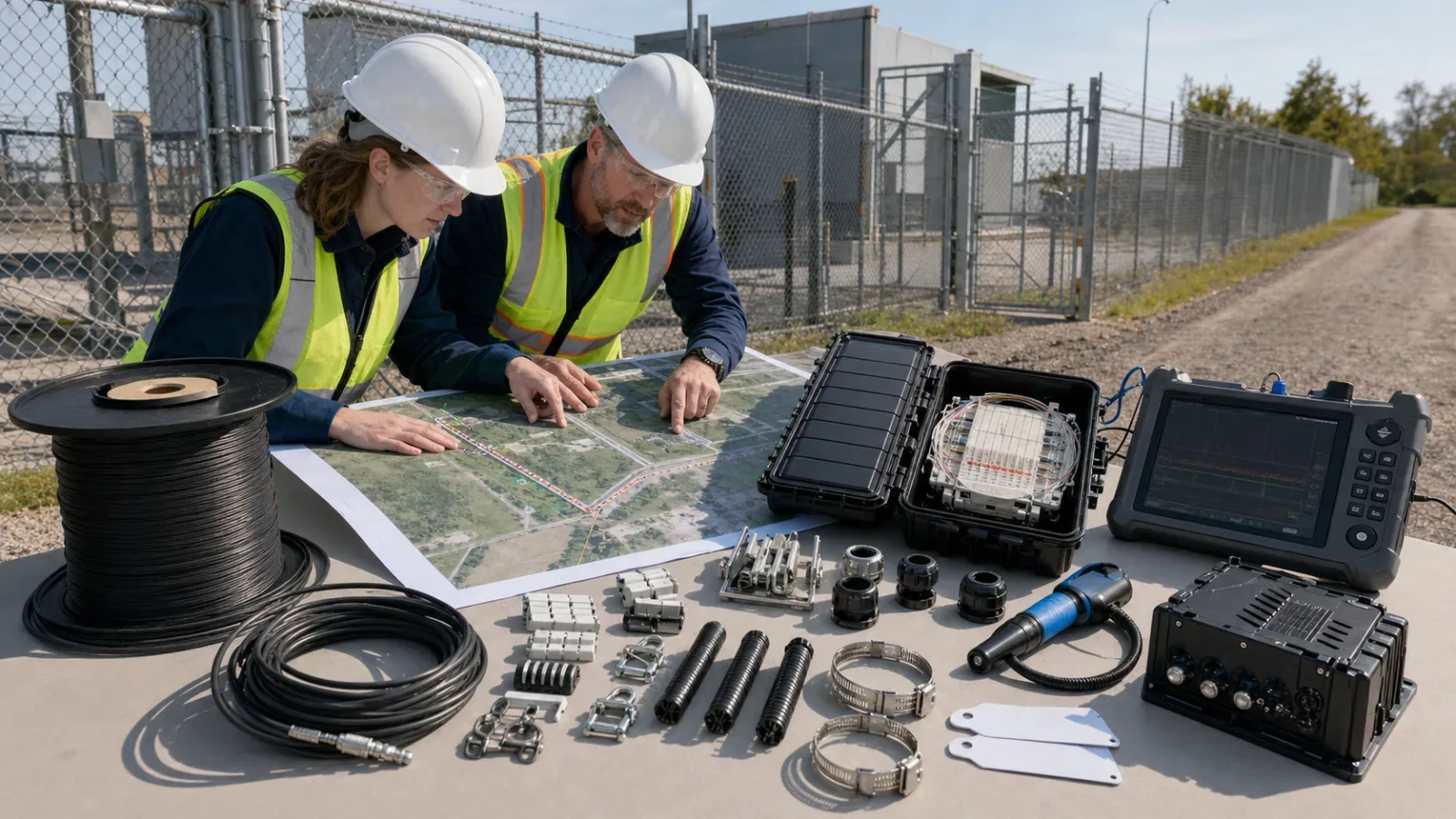
Require an Acceptance-Ready Handover Package
Approved final BOM with manufacturers, part numbers, quantities, and substitutions.
As-built sensing, lead, splice, cabinet, route, and alarm-zone drawings.
Cable drum, receiving-inspection, installation, splice, and enclosure records.
Optical inspection and test reports required by the contract.
Controller, network, integration, time, and configuration backups.
Asset, enclosure, splice, termination, cable, and port label registers.
Alarm, health, communication, camera, and failure-state mapping.
Commissioning, acceptance, deviation, open-defect, and retest evidence.
Operations, maintenance, training, warranty, support, and final spare inventory.
CommScope field-testing guidance describes completed cabling verification as inspection, testing, and documentation, including pathways, cabinets, cable placement, terminations, connector end faces, labels, and optical tests where appropriate. The contract and selected sensing system must decide which specific tests apply.
IEC 61757:2026 is the current generic specification for fiber optic sensors, while IEC 61757-3-2:2022 defines terminology, performance parameters, and test methods for phase-sensitive OTDR distributed acoustic and vibration interrogators. These standards can support performance specifications; they do not supply a universal fence-retrofit BOM or mounting quantity.
Turn the Survey Into a Procurement Package
A reliable fiber PIDS BOM is a controlled output of the operational requirement, survey, topology, selected product instructions, integration schedule, and acceptance plan. Every cable length, attachment, gate assembly, enclosure, interface, test item, spare, and deliverable should map to a physical location or engineering requirement.
After the BOM is approved, implement it through a controlled chain-link fence attachment design rather than leaving cable path, posts, corners, toppings, and gate handoffs to field improvisation.
For critical sites, review the wider critical infrastructure perimeter-security architecture and the United States deployment context. For a project-specific takeoff, request a FortSense design review before procurement quantities are frozen.
For a rigid-panel retrofit, pair this component schedule with the welded-mesh installation design before freezing attachments and quantities.