A chain-link fiber PIDS installation succeeds only when the sensing cable, attachment method, host fence, posts, corners, toppings, transitions, and maintenance access work as one mechanical detection system. The cable should follow the approved product design on the secure side, remain protected from damage, and receive repeatable fence vibration without relying on improvised spacing or excessive tension.
Do not install the sensor over slack, torn, corroded, heavily patched, vegetation-loaded, or structurally unstable mesh and expect calibration to compensate. Repair the barrier first, document each fence condition, then qualify the complete attachment design with representative climb, cut, lift, nuisance, and verification tests.
NPSA barrier-mounted PIDS guidance explains that performance depends on matching the sensor to the barrier: a fence that is too rigid may not transmit the required vibration, while one that is too flexible can react strongly to wind or rain. It also recommends mounting barrier PIDS on the secure side and verifying alarms through the security workflow.
Chain-Link Attachment Design in One Checklist
Confirm the chain-link fence is a suitable host barrier for the operational requirement and selected product.
Survey mesh condition, tension, posts, rails, foundations, toppings, repairs, corners, gates, and environmental exposure.
Freeze the sensing path, number of passes, zone boundaries, lead cable, enclosures, and transition details before takeoff.
Use only the cable, attachments, tools, spacing, tension, bend limits, and protective parts approved for the selected system.
Keep sensor equipment on the secure side and protect reachable transitions, loops, connectors, and enclosures from tampering.
Treat posts, corners, height changes, toppings, gates, and walls as engineered details rather than ordinary fence fabric.
Commission the final installation with threat, nuisance, integration, power-loss, and maintainability evidence.
If the product class is still undecided, start with the fiber-optic fence sensor buyer guide. This page begins after a candidate chain-link-mounted system has been selected.
First Decide Whether the Chain-Link Fence Is an Acceptable Host
PIDS adds detection; it does not turn a weak fence into a high-delay security barrier. NPSA describes barrier-mounted PIDS and the host barrier as working together, while its security fences and gates guidance does not recommend chain-link fabric as a security fence for higher protective requirements. The site operational requirement must therefore decide whether an existing chain-link retrofit is acceptable, temporary, layered, or due for barrier replacement.
Mesh gauge, opening, coating, corrosion, tears, deformation, and repairs.
Fabric tension, bottom clearance, tension wire, top rail, and attachment to terminal and line posts.
Post alignment, foundations, braces, bands, rails, and local movement.
Barbed wire, razor ribbon, outriggers, anti-climb additions, and their stability.
Public contact, wildlife, vegetation, drainage, wind exposure, traffic, and routine maintenance.
Different fence eras or contractors that created materially different bays along one route.
Record every change as a route segment. A single calibration cannot be assumed to cover unlike mesh condition, height, support, topping, or exposure.
Repair the Fence Before Installing the Sensor
Replace or repair torn fabric, loose tension bands, bent rails, unstable posts, failed foundations, and improvised patches before attaching sensing cable. Remove vegetation that contacts or loads the fence and correct debris paths that can repeatedly strike it.
A repair acceptance record should identify the bay, defect, action, photographs, date, and person accepting the host barrier. This creates a baseline for later maintenance and helps distinguish sensor problems from fence deterioration. NPSA maintenance guidance notes that loose or degraded cable ties, corrosion, vegetation growth, and site changes can alter PIDS performance over time.
Place the Sensing Path on the Secure Side
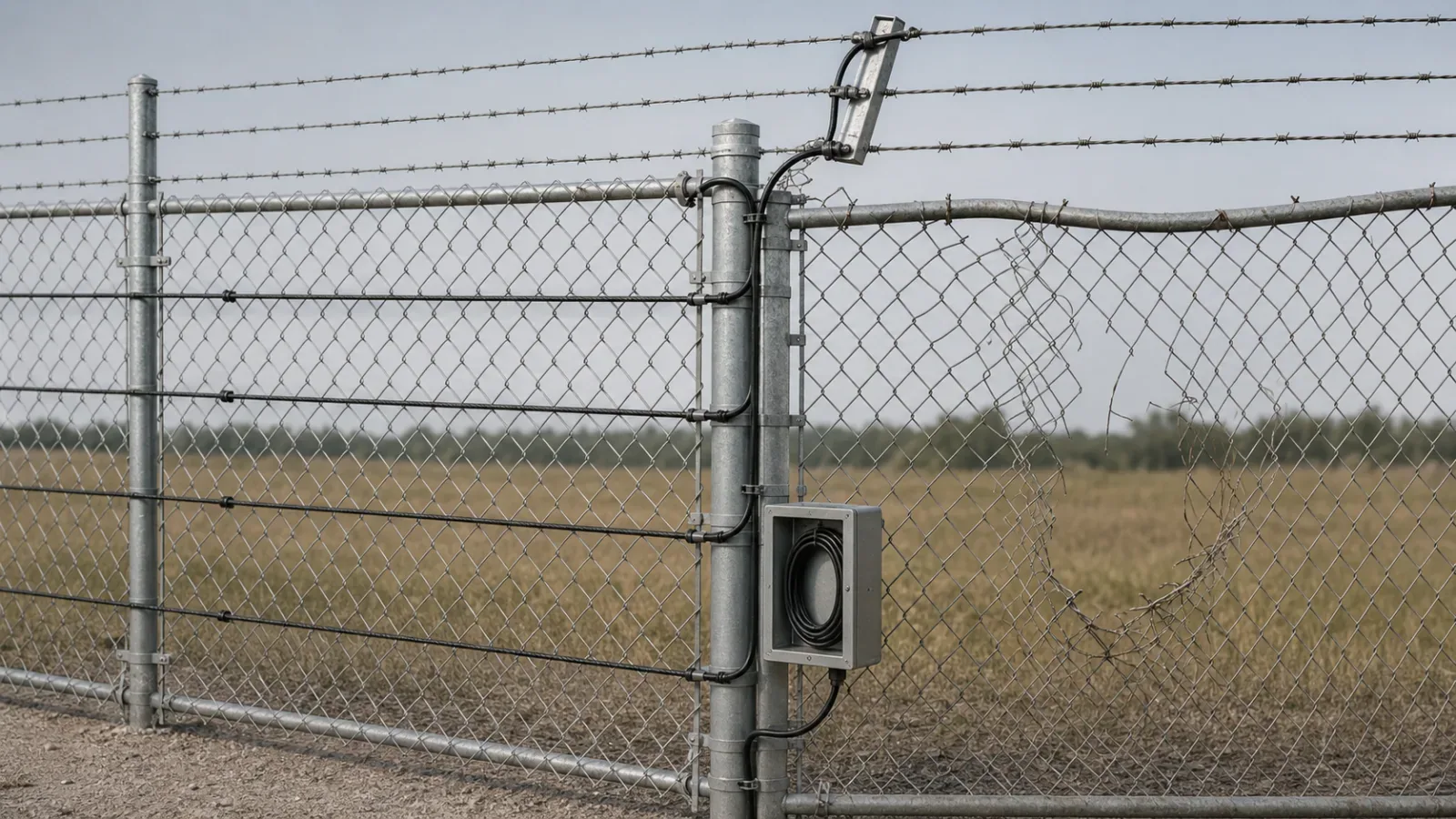
Keep the sensing cable, junctions, service loops, and associated equipment on the defended side wherever the selected design permits. This reduces direct access and keeps maintenance activity inside the controlled perimeter. Outdoor equipment needs suitable environmental protection and tamper consideration.
The sensing path should follow the moving fence fabric where the product is intended to detect fabric vibration, while posts, rails, and rigid structures are handled exactly as the manufacturer design specifies. Do not move a cable onto a convenient rigid member without evidence that the required attack energy reaches the sensor.
Map the approved path through the fiber optic PIDS cable-route design process and convert the frozen path into the fiber PIDS retrofit bill of materials. Route and procurement must describe the same installation.
Do Not Copy Attachment Spacing From Another Product
There is no universal cable-tie interval, number of sensing passes, mounting height, tension, or attachment material for every fiber PIDS and chain-link fence. Those values depend on the selected cable, detection method, fence construction, topping, threat set, environment, and evaluated configuration.
The NPSA VibraSector chain-link listing is a useful warning against copying numbers: it documents one assessed product on one defined chain-link construction with a particular cable path and attachment interval. That configuration is evidence for that product, not a generic fiber-sensor specification.
Likewise, manufacturer guides can require different attachments for unarmored cable, armored cable, fence fabric, barbed wire, or razor ribbon. Use the current manual and approved tooling for the exact product revision. Reserve detailed interval and tension engineering for the dedicated attachment-spacing specification and field acceptance plan.
Engineer Posts, Corners, and Height Changes
Terminal posts, corner posts, braces, rail ends, and changes in fence height can concentrate movement, create sharp edges, or isolate one fabric panel from the next. Preserve approved bend radius, protect the cable from abrasion, and avoid loops that can snag, flap, or become a tamper target.
Document the cable path into and out of each transition, the protective sleeve or conduit, attachment hardware, enclosure, service loop, and route reference. A corner or height change should be repeatable enough that an inspector can compare the installed detail with the drawing and manufacturer instruction.
Treat Barbed Wire and Razor Toppings as Separate Details
Toppings move differently from chain-link fabric and introduce sharp edges, outriggers, coils, and maintenance hazards. Do not extend the fence-fabric attachment pattern onto a topping without a product-specific method.
A current Senstar FlexZone installation guide provides a manufacturer-specific example requiring different handling for armored cable, barbed wire, outriggers, and razor ribbon, including bend and abrasion precautions. Use such documents only for the named system; they demonstrate why topping details must be explicit.
Hand Gates and Moving Openings to Their Own Design
Swing gates, sliding gates, emergency exits, and vehicle openings are not ordinary chain-link bays. Movement envelopes, hinges, rollers, latches, flexible protection, loops, bypasses, gate state, auxiliary sensors, and camera logic can change the architecture.
End the fixed-fence design at a controlled handoff point and reference the gate assembly drawing. Do not route sensing cable across a moving member simply to preserve continuity. Where a product does not support the gate, use a suitable point, microwave, access-control, or video layer and test the complete alarm workflow.
Design for Inspection and Replacement
Keep labels and drawings consistent with fence bays, zones, posts, enclosures, and camera sectors.
Provide safe access to attachments, protected loops, splice points, and transition hardware.
Record cable and tie material, tool setting or approved method, installer, date, and product revision.
Define how damaged cable, degraded ties, fence repairs, vegetation, corrosion, and site changes are inspected.
Specify when configuration backup, recalibration, threat testing, or bounded retesting is required after maintenance.
If the supplier cannot prove the chain-link design under representative conditions, hold procurement and use the fiber PIDS proof-of-concept plan. If coupling, barrier condition, route, or response remains unsuitable, apply the DAS no-fit decision framework.
Commission the Complete Attachment System
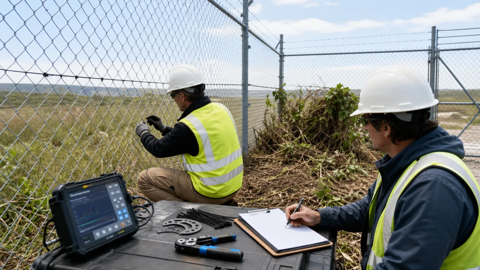
Visual conformity: approved path, secure-side mounting, attachment condition, cable protection, bends, transitions, enclosures, labels, and fence repairs.
Threat evidence: representative climb, cut, lift, and tamper events across typical bays and transitions defined by the operational requirement.
Nuisance evidence: wind, rain, vegetation, traffic, wildlife, maintenance, and gate activity observed during the test window.
Zone and verification: alarm location, camera view, control-room presentation, acknowledgement, and response match the approved design.
Resilience and health: power loss, communication loss, cable fault, tamper, degraded state, and recovery behavior are visible and actionable.
Maintenance baseline: photographs, configuration, optical records, test results, deviations, and accepted attachment details are preserved.
NPSA recommends commissioning after installation and before acceptance, with the integrated system tested as a whole. A visually tidy cable run is not accepted until its detection, unwanted-alarm, verification, resilience, and maintenance evidence meets the project requirement.
Final Design Rule
Attach fiber PIDS to chain-link only after the host barrier is accepted, the route and transitions are engineered, the exact manufacturer method is frozen, and field evidence proves the complete system. Do not use calibration to conceal a bad fence, copy spacing from another product, or leave gates and toppings as installer improvisation.
For critical sites, review the critical infrastructure perimeter application, the United States deployment context, and how FortSense 4 maps physical fiber zones into alarm and verification workflows. To review a site-specific chain-link design, request a FortSense engineering consultation.
For rigid panel barriers, use the welded-mesh fiber PIDS installation guide to engineer panel, seam, post, coating, and commissioning details.