Border-security DAS uses a long fiber optic route as a continuous vibration sensor for remote corridors, fence lines, service roads, washes, culverts, gates, and other approach paths. The right design is not just a longer perimeter sensor. It is an operational system that turns route-level acoustic events into verified camera views, patrol tasks, escalation rules, and evidence that a command center can trust.
The hard part is not sensing movement somewhere along a remote border. The hard part is proving which events matter, where they happened, what camera or patrol asset should verify them, how nuisance vibration is suppressed, and what the operator should do when communications, power, weather, or road traffic degrade the signal.
This guide is intentionally separate from DAS detection range claims, localization accuracy claims, and fiber PIDS proof-of-concept testing. Those pages handle vendor claim validation. This page handles border corridor architecture and response design.
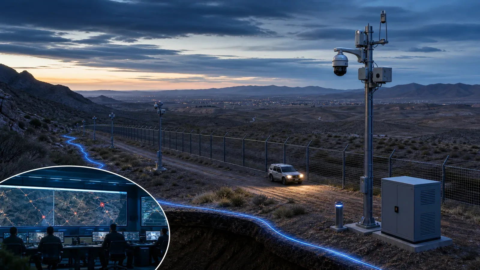
Start with the border operating requirement
A border DAS design should begin with an operating requirement, not a fiber route drawing. NPSA guidance on operational requirements is useful because it forces the project to define the asset, threat, outcome, constraints, and acceptance criteria before selecting technology. For borders, the same discipline prevents a common failure: buying a sensor that detects activity but does not create an actionable response.
Define the corridor purpose: illegal crossing detection, approach warning, fence climb or cut detection, smuggling route awareness, vehicle interdiction support, infrastructure protection, or evidence collection.
Name the response owner for each zone: command center operator, patrol unit, camera operator, local guard post, law-enforcement partner, or a higher command function.
Separate detection classes: footsteps, crawling, climbing, cutting, digging, vehicle approach, vehicle stop, repeated probing, gate movement, and utility or road vibration.
Define verification method: fixed camera, thermal camera, PTZ camera, radar cue, patrol dispatch, drone tasking, or multi-sensor correlation.
Set acceptance criteria in operational language: probability of detection for named scenarios, maximum nuisance alarm rate by terrain, localization accuracy by segment, and maximum operator action time.
Useful external anchors for this phase are the NPSA guide to operational requirements for security measures and the acoustic/vibration measurement vocabulary in IEC 61757-3-2. They do not design the border system for you, but they keep the procurement language testable.
Where DAS fits in a border-security stack
DAS is strongest when the site needs continuous awareness across a long linear route where conventional point sensors, fence-only alarms, or camera-only monitoring leave gaps. It can be attached to a fence, buried near an approach path, routed beside a service road, or reused from available fiber when the optical and operational conditions are acceptable.
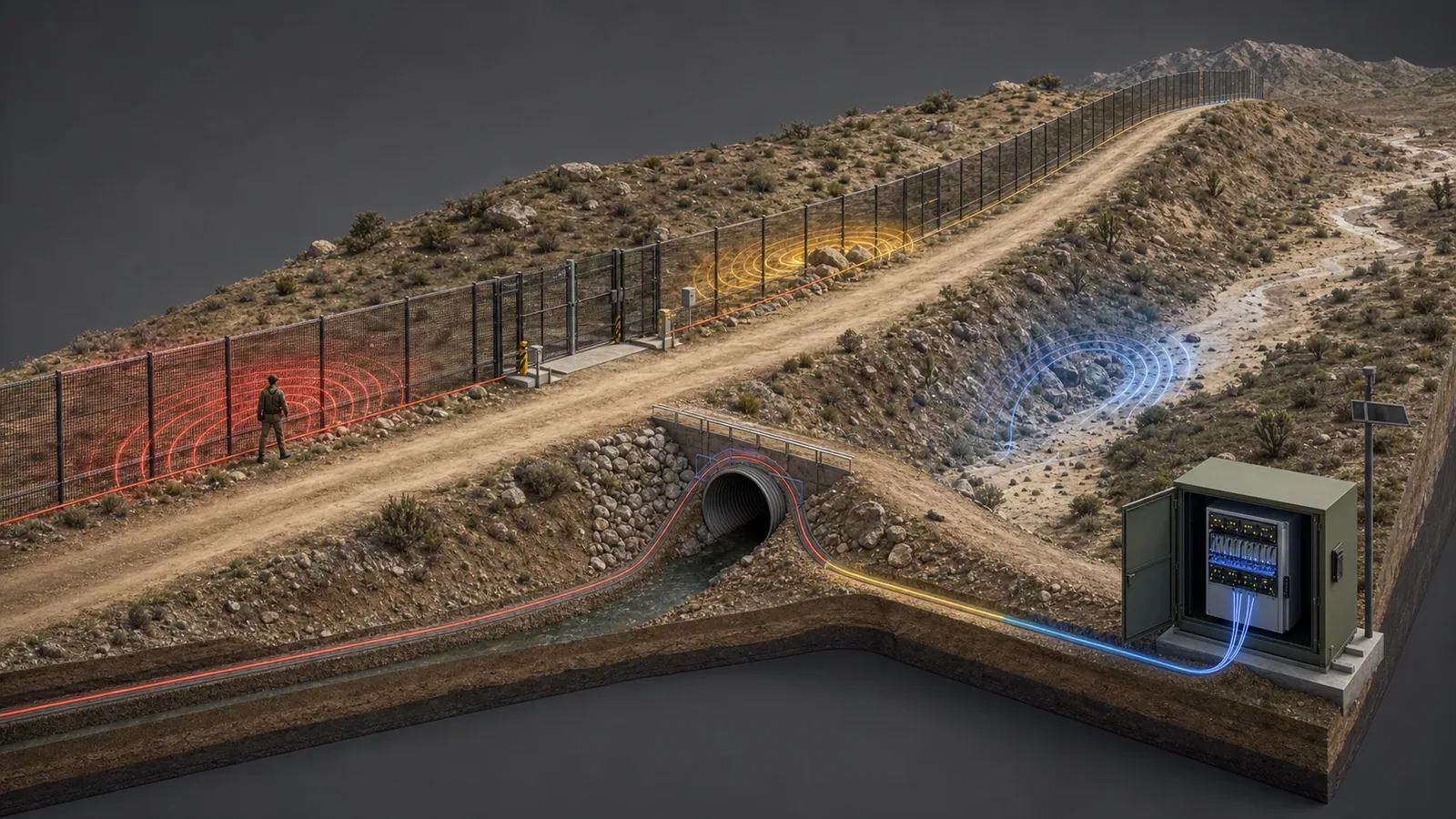
Fence-mounted fiber is useful when the main concern is climb, cut, impact, and fence manipulation.
Buried fiber is useful when the main concern is covert approach, footsteps, vehicles, digging, or activity before the fence.
Service-road routes are useful when vehicles, patrol movement, and road vibration must be classified rather than treated as noise.
Culvert, gate, bridge, and wash transitions need special design because coupling and nuisance conditions change quickly.
Long remote sectors need edge cabinets, power, communications, time sync, health monitoring, and local failover that match the patrol model.
If the project is primarily a standard facility perimeter, start with the broader fiber optic IDS guide for long perimeters. If the project requires bidirectional enterprise connectivity across an isolated border network, review data diode integration for isolated perimeter security networks before connecting monitoring systems.
Route engineering decisions that matter
The sensor route decides what acoustic energy reaches the fiber. A specification that only says “cover 60 kilometers” is weak. The design must describe how the fiber is mounted or buried, how each terrain segment couples vibration, how transitions are handled, and how maintenance teams will prove that the route still matches the commissioned baseline.
Segment the corridor by terrain, fence type, access road, wash, bridge, culvert, gate, utility crossing, and patrol pattern.
Record chainage or route distance, GIS geometry, elevation, cabinet locations, splice points, and every transition where acoustic coupling changes.
Define zone length for operations, not just sensing. A zone that is too long may be technically detectable but operationally slow to verify.
Model nuisance sources: wind loading, rain, animals, road traffic, rail vibration, maintenance vehicles, generators, nearby works, and patrol movement.
Keep camera and patrol coverage aligned with the detection route. A precise alarm that points to a blind camera sector still fails the operator.
Detection classes and nuisance suppression
Border corridors create dense acoustic noise. DAS tuning must distinguish intrusion signatures from repeated environmental and operational signatures, then expose confidence and degradation to operators. Over-tuned systems miss slow or novel activity. Under-tuned systems flood the command center until operators ignore the sensor.
Build signature libraries from the actual route: walking, running, crawling, climbing, cutting, digging, stopping vehicles, passing vehicles, patrol vehicles, animals, wind, rain, and maintenance work.
Use environmental baselines by segment. Rocky ground, sand, clay, culverts, bridges, and fence posts do not behave the same way.
Feed camera verification and patrol outcomes back into tuning decisions without letting operators silently relabel unresolved events as false alarms.
Track nuisance alarm rate by segment, time of day, weather, and road condition. A single global false-alarm number hides the sectors that need engineering work.
Retain enough acoustic trace, event metadata, and operator disposition to support forensic review and threshold changes.
For camera confirmation, use the same design discipline described in geospatial perimeter alarm-to-camera mapping and thermal cameras for perimeter security. DAS should cue verification; it should not leave operators searching a blank map.
Command-center and patrol workflow
A border DAS alarm must arrive with enough context for a fast decision: event class, confidence, route distance, map position, nearest camera, nearest patrol access point, sector owner, last health state, recent nuisance context, and response procedure. Without that context, a sophisticated sensor becomes another noisy feed.
Map each event to a patrol-access route and estimated response time, not only to a latitude and longitude.
Pre-stage camera presets or verification views for every sector with clear handoff when the best camera is unavailable.
Use alarm priority rules that consider event type, repeated activity, direction of travel, proximity to vulnerable assets, and current sensor health.
Show stale-data, communications outage, backlog, degraded power, cabinet tamper, and fiber fault states in the same operator workflow as intrusion alarms.
Document who can close an alarm, what evidence is required, and how unresolved alarms are reviewed.
The U.S. border-surveillance record also shows why measurement matters. GAO has repeatedly criticized border technology programs when performance measures and mission contribution are not clear enough. A DAS project should therefore define operational measures before rollout, not after installation. See GAO border surveillance technology reporting and CBP’s public overview of border technology such as towers, sensors, cameras, and communications in U.S. Border Patrol technology.
Acceptance test plan for a border DAS deployment
A border deployment should not pass acceptance with a vendor walk test near a cabinet. It needs representative trials across the actual corridor, including difficult terrain, long distance, camera handoff, patrol workflow, nuisance sources, and failure modes.
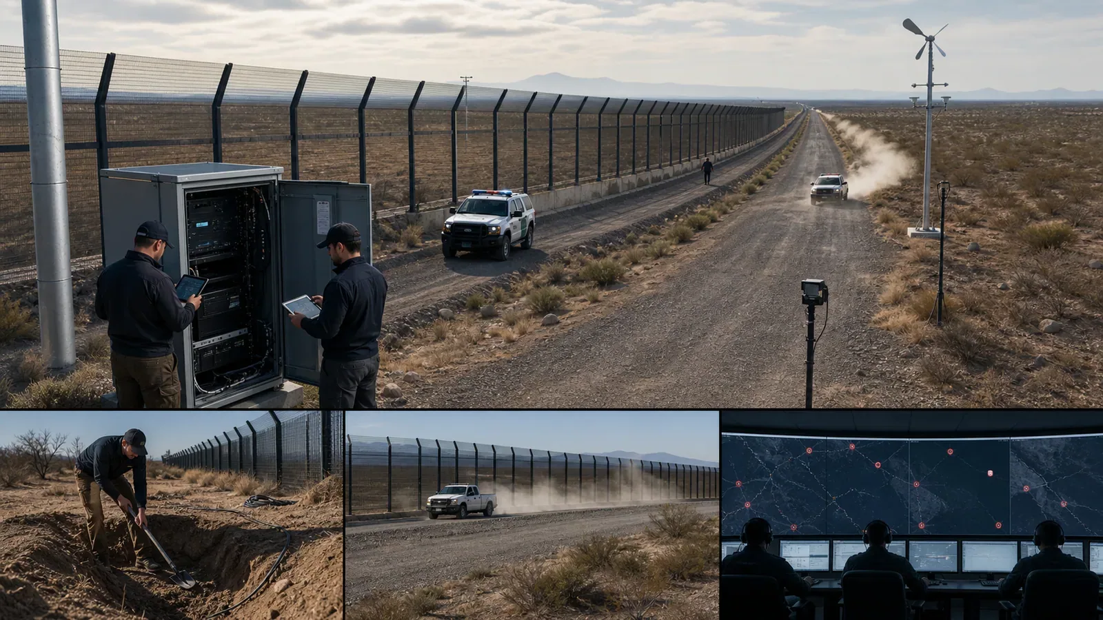
Precommission with OTDR, splice-loss records, cabinet inventory, power status, time-sync status, and route GIS data.
Run blind intrusion tests by segment: walking, crawling, climbing, cutting, digging, vehicle approach, vehicle stop, and repeated probing where relevant.
Test nuisance scenarios: patrol vehicle pass, public-road traffic, wind, rain or simulated weather, animal movement where common, generator vibration, and maintenance work.
Measure localization error by terrain and route segment, then compare it with camera field of view and patrol access routes.
Verify camera slew or fixed-view selection, video pre-roll, operator acknowledgement, patrol dispatch, and evidence retention.
Fail cabinets, power, communications, receiver services, and fiber segments. Confirm degraded states are visible and local response procedures still work.
Document probability of detection, nuisance alarm rate, localization error, operator action time, and unresolved-event review for every representative sector.
When DAS is the wrong technology for a border sector
DAS should not be forced into every border sector. It may be the wrong primary sensor when the route cannot be coupled to the threat activity, where maintenance access is unrealistic, where power and communications cannot support the cabinet plan, where camera or patrol verification is impossible, or where the mission requires identification rather than detection.
That decision should be explicit. Use When DAS Is the Wrong Perimeter Detection Technology to pressure-test the negative case before buying a long fiber route. Use Can Existing Dark Fiber Be Reused for Perimeter DAS? when the project is considering existing telecom fiber instead of a purpose-built sensing route.
Border DAS design checklist
Operational requirement names the threat, expected outcome, response owner, and acceptance criteria.
Fiber route is segmented by terrain, fence, road, culvert, gate, cabinet, splice, and camera coverage.
Detection classes are tied to real response procedures and evidence requirements.
Nuisance sources are measured by segment and tested during commissioning.
Geospatial alarm mapping connects route distance to map position, camera view, and patrol access.
Health monitoring covers cabinets, power, communications, time sync, fiber faults, and stale data.
Acceptance tests include blind trials, nuisance trials, camera handoff, patrol workflow, and failure modes.
The design includes a clear “do not use DAS here” boundary for sectors where another sensor is better.
For a project-specific border or long-corridor review, bring the operational requirement, route map, terrain segments, camera plan, patrol model, communications plan, and current nuisance sources. FortSense can review whether DAS, fence-mounted fiber, buried fiber, thermal verification, or a hybrid stack is the right architecture. Start with FortSense 4, critical infrastructure perimeter security, or contact FortSense.