Existing dark fiber can sometimes be reused for perimeter distributed acoustic sensing, but an unused strand is only a candidate. Reuse is defensible only when the route is close enough and mechanically coupled to the monitored boundary, the complete optical path is compatible with the proposed interrogator, access and maintenance rights are controlled, and a site proof of concept passes the project’s security requirements.
A clean OTDR trace establishes optical information. It does not prove that cutting, climbing, walking, digging, or vehicle activity will couple enough energy into the cable for reliable detection.
The technical possibility is real: a U.S. Department of Energy dark-fiber field example used existing unused telecom fiber for distributed sensing. Perimeter acceptance still requires a separate route-specific evaluation.
Use four independent feasibility gates
Documentary and access eligibility: ownership, strand assignment, endpoint access, maintenance rights, and future control.
Physical sensing suitability: route proximity, mechanical coupling, cable construction, and environmental context.
Optical qualification: complete topology, fiber condition, connectors, splices, reflectance, loss, loops, and end access.
Operational acceptance: site POC, threat-event detection, unwanted alarms, localization or zones, integration, and resilience.
Failure at one gate cannot be cancelled by success at another. Good optical health does not repair poor coupling, and strong staged detection does not resolve uncontrolled ownership or maintenance access.
Define what dark-fiber reuse means
Dark fiber is installed optical fiber not currently carrying a communications service. For this assessment, the preferred baseline is a dedicated unused strand connected to a DAS interrogator.
Dedicated dark strand: optically separate from communications, while route and cable-maintenance risks may still be shared.
Spare strand in a live cable: optically separate, but cable cuts, closure work, restoration, rerouting, and future strand allocation remain shared risks.
Same active strand: communications and sensing coexist through wavelength and optical-system engineering. This requires a separate specialist compatibility study.
Gate 1: verify ownership, records, and access
Start with documents, not an interrogator. Request:
Cable and strand ownership and the right to connect sensing equipment.
Patch-panel, handhole, closure, and equipment-room access.
Current route drawings, as-built records, and strand assignments.
Maintenance, restoration, and post-change validation responsibilities.
Notification and change-control requirements before fiber work.
Planned activation, rerouting, network expansion, or strand reassignment.
Access to one or both ends for testing.
Cybersecurity requirements for connected sensing equipment.
A strand marked “spare” is not automatically available for a security function. DAS availability becomes part of the perimeter architecture, so unannounced patching or restoration cannot remain ordinary telecom maintenance.
Gate 2: confirm route and mechanical sensing suitability
DAS depends on the complete mechanical path from the threat event, through fence, soil, pavement, or structure, into the cable jacket and optical fiber. Route proximity and cable construction affect how disturbances transfer into the sensing strand.
GEUS distributed acoustic sensing guidance and a peer-reviewed comparison of telecom cable constructions support site-specific evaluation of coupling and cable response; neither source creates a universal cable ranking.
Inspect route proximity
Protected fence, wall, buried boundary, gates, and vehicle entrances.
Roads, rail, pumps, transformers, machinery, and other persistent vibration sources.
Utility corridors, drainage, soil, pavement, ducts, bridges, and building transitions.
Parallel, doubled-back, and off-site sections.
Areas where the cable leaves the protected boundary.
Map distance alone is insufficient. A nearby cable in a mechanically isolated duct may respond differently from fiber attached to a fence or installed in controlled backfill. There is no universal acceptable standoff distance. For new or remediated sections, use the fiber optic PIDS cable-route design guide.
Inspect fiber and cable construction
Fiber category and manufacturer records where available.
Loose-tube, tight-buffered, ribbon, armored, or microcable construction.
Ducted, direct-buried, aerial, fence-mounted, or building-mounted sections.
Known repairs, water exposure, crush events, and bend risks.
Changes in cable design or installation along the route.
ITU-T G.652:2024 defines attributes for a major single-mode fiber family. Fiber category is useful evidence, but it does not certify perimeter sensing performance.
Gate 3: reconstruct and test the complete optical path
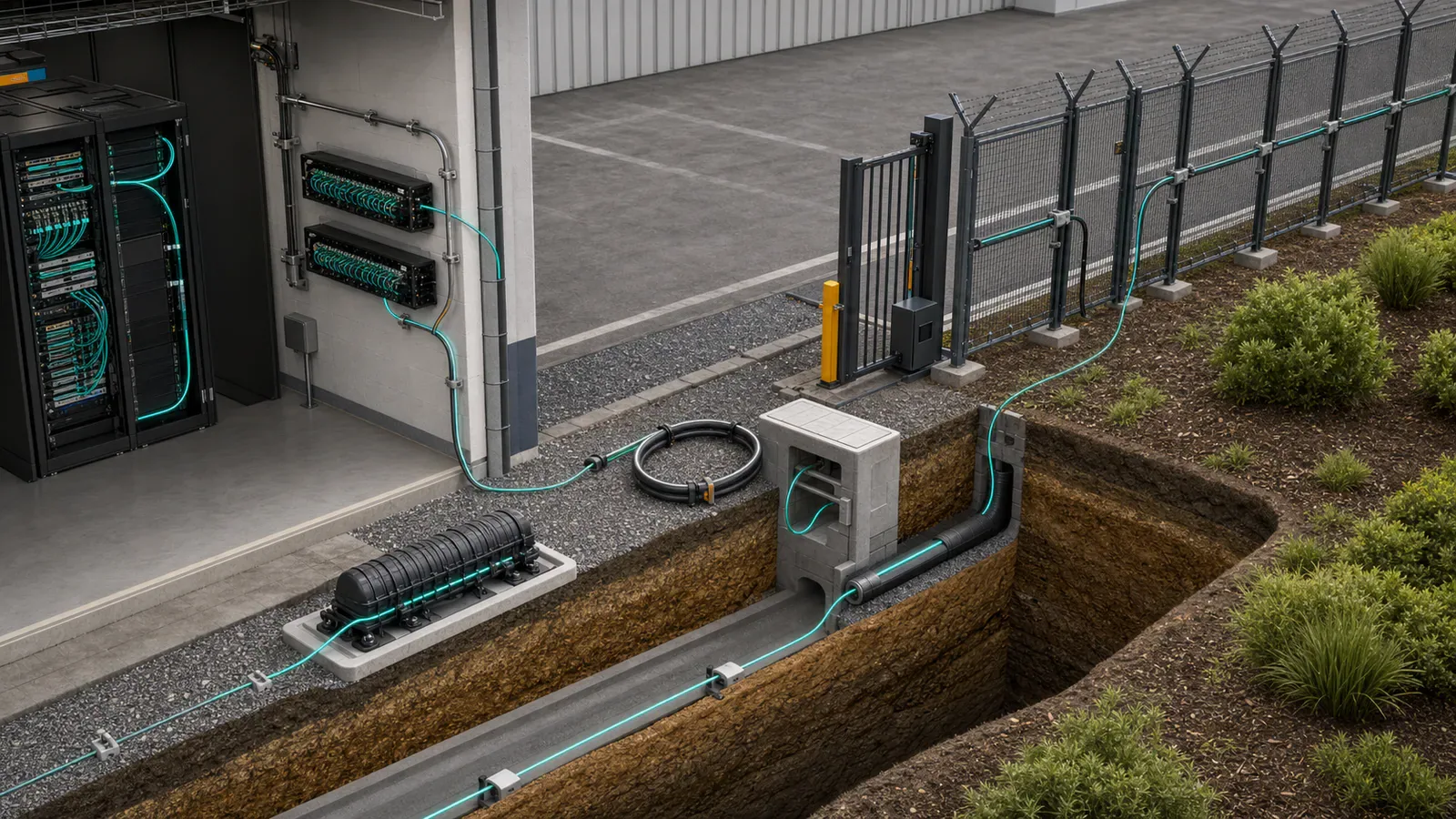
Build an optical path drawing that identifies:
Interrogator connection and non-sensing lead-in.
Patch panels, connectors, and fusion or mechanical splices.
Maintenance coils, slack loops, cross-connects, and route transitions.
Splitters, wavelength-selective components, amplifiers, or other active elements.
Branches, inaccessible sections, doubled-back routes, and end termination.
Accessible test points and any difference between optical and physical route length.
Lead-ins, loops, detours, and return paths consume optical distance without necessarily protecting more perimeter. Create a chainage table connecting optical position to physical section, installation type, landmark, gate, splice, loop, camera view, and response zone. If continuous location is required, apply the fiber PIDS localization acceptance framework.
Request OTDR and insertion-loss evidence
ITU-T G.650.3 covers testing installed single-mode links. Current IEC TR 62316:2026 provides guidance for interpreting OTDR backscattering traces for single-mode fibers.
Test instrument, calibration status, wavelength, pulse, and acquisition settings.
Launch and receive fibers plus connector inspection and cleaning records.
Full traces, event tables, optical length, and end event.
Splice and connector locations, event loss, and reflectance.
Suspected bends, nonuniform attenuation, or unexplained discontinuities.
End-to-end insertion-loss evidence where required.
Measurement direction and access limitations.
Bidirectional traces are preferable for careful splice evaluation because backscatter differences can create apparent gain or exaggerated loss in one direction. If only one end is accessible, record that limitation instead of treating one-way results as definitive. See the Fiber Optic Association OTDR reference.
Know what OTDR cannot prove
Detection of required threat events.
Mechanical coupling to fence, soil, or structure.
Classification performance.
Physical-map localization accuracy.
Unwanted-alarm behavior.
Camera and control-room integration.
Stability under weather and normal operations.
Do not use a generic loss, splice, connector, or reflectance threshold. Compare the measured path with the selected interrogator’s documented requirements, then verify sensing performance during the POC. For usable reach, apply the DAS range-claim framework.
Treat shared-cable and wavelength risks separately
A dedicated dark strand can still share a cable with operational communications. Assign responsibility for closure access, restoration route, spare-strand allocation, loop changes, chainage updates, advance work notice, and post-maintenance sensing regression tests.
A spare strand in the same cable is not wavelength coexistence. Same-strand communications and sensing require specialist review of wavelengths, launch power, direction, filtering, multiplexers, amplification, receiver limits, sensing performance, safety, and change control. ITU-T G.681 provides a standards framework for distributed fiber-optic sensing in terrestrial optical transmission systems, but it is not a universal compatibility guarantee.
Decision rule: treat a dedicated dark strand as the baseline. Treat same-strand coexistence as a separate optical-network design, never as an assumed DAS feature.
Gate 4: run a site proof of concept
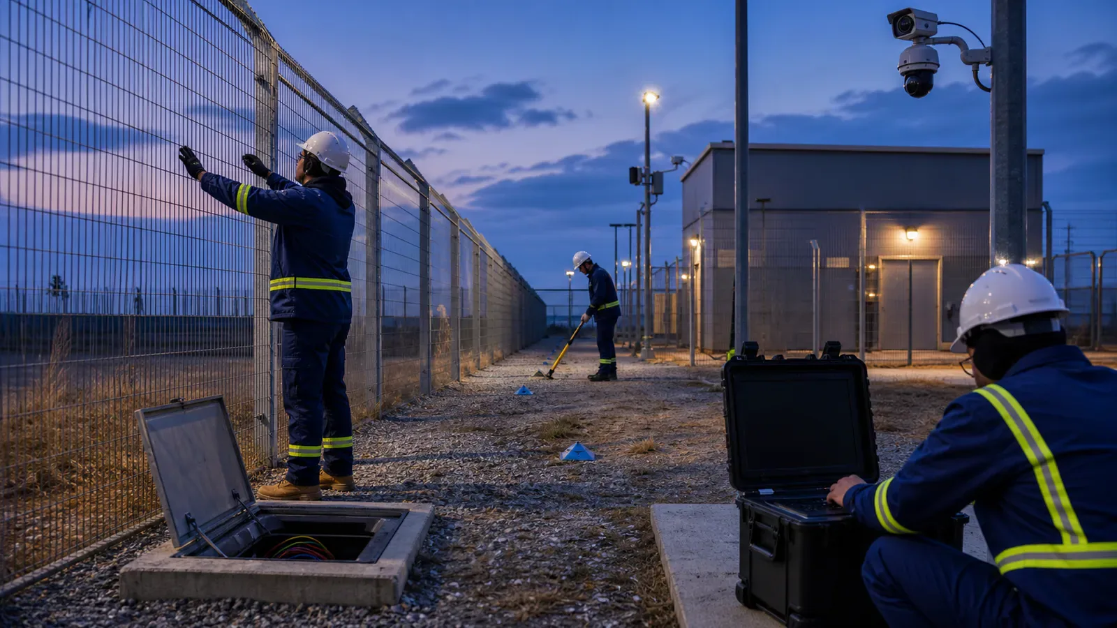
Test the installed route with the proposed interrogator and production-oriented settings. A laboratory spool cannot reproduce route coupling, repairs, background vibration, transitions, and integrations.
1. Establish the baseline
Approve route and topology drawings and capture the optical test baseline.
Map optical positions to controlled physical landmarks.
Record traffic, machinery, weather, vegetation, and maintenance activity.
Identify likely strong, typical, and weak sections.
2. Define the threat-event matrix
Use the Operational Requirement to select fence, buried-route, vehicle, excavation, cable-tamper, gate, and corner events. Test near, middle, and far optical positions, then stratify by physical condition: fence type, duct, soil, pavement, crossing, splice, loop, transition, noisy area, and suspected weak section.
3. Separate tuning from acceptance
Use one event set for calibration. Then freeze the interrogator, gauge length, mapping, filters, thresholds, classifier, zones, firmware, and software before acceptance trials.
4. Test detection and unwanted alarms separately
NPSA PIDS guidance treats attack detection and false-alarm performance as separate evidence. Record every scheduled trial, miss, wrong location, unexplained alarm, integration timestamp, camera selection, and operator-visible result. Run a representative background soak using project-defined criteria.
5. Test resilience and integration
Fiber-cut indication and remaining coverage.
Power, network, and time-synchronization recovery.
Health monitoring and configuration restoration.
VMS, SCADA, PSIM, relay, camera, and SOC workflow.
Behavior after patching, repair, or route-record updates.
Use the perimeter detection acceptance-testing guide for broader handover evidence.
Make an explicit reuse decision
Accept for continuous DAS: route, optical path, access model, POC, and operational workflow meet requirements. Evaluate FortSense Ultra.
Accept with remediation: targeted connector, patching, loop, mapping, or route work can resolve identified weaknesses.
Accept only selected sections: combine reusable fiber with dedicated sensing sections or other PIDS. Review retrofit versus greenfield design and mixed-perimeter sensing.
Reject continuous reuse: route geometry, coupling, topology, access, or field performance cannot support a defensible system. If physical response zones fit better, evaluate FortSense 4.
Only after feasibility is established should the owner apply the fiber PIDS TCO procurement model. Reuse may reduce some civil work, but investigation, remediation, records, access, and operational risk remain project-specific inputs.
Final decision rule
Existing dark fiber is reusable for perimeter DAS only when the organization controls it, the route transfers required events into the cable, the complete optical path is compatible with the selected interrogator, and the installed system passes a site-specific POC and acceptance process.
For context, review the fiber optic fence sensor buyer guide, long-perimeter fiber design, critical-infrastructure perimeter security, and United States deployment context.
Review the actual strand and route
When the available strand fails route, coupling, ownership, resilience, or operational tests, review when DAS is the wrong perimeter technology and select a zone, point, buried, wide-area, video, or hybrid alternative.
Bring the route drawing, strand assignment, OTDR traces, access constraints, maintenance process, and threat requirements to a FortSense dark-fiber design review.
When existing fiber is being considered for a border corridor, pair this feasibility check with the border-security DAS design guide.