A DAS detection range claim is credible only when the system detects the required intrusion events across the claimed route, within agreed localization, latency, and unwanted-alarm limits, under representative site conditions. Maximum interrogated fiber length alone does not establish usable perimeter coverage.
That distinction should control how distributed acoustic sensing systems are compared. A specification such as "up to X kilometers" describes an engineering envelope. It does not tell a buyer how much of that route can protect a particular fence, buried approach, pipeline corridor, or mixed perimeter.
For broader vendor-selection criteria, start with the fiber-optic fence sensor buyer guide. The framework below addresses the narrower question: how should a DAS range claim be verified before procurement?
DAS detection range is not one number
Ask the supplier to separate six different measurements:
Interrogated fiber length: the total optical path the interrogator can read under stated conditions.
Sensing fiber length: the portion intended to respond to events. Lead-in fiber, service loops, and return paths may consume optical reach without protecting additional perimeter.
Protected route length: the physical fence, wall, buried boundary, or corridor covered by the installation.
Usable detection coverage: the contiguous route over which required events meet the project detection criteria.
Localization performance: how accurately the system reports where an event occurred along the route.
Standoff detection distance: for buried or corridor applications, the lateral distance from the fiber at which a defined event remains detectable.
These measurements are related but not interchangeable. A system may interrogate the entire fiber while failing to classify a weak event near the far end. A looped cable may use two kilometers of fiber to protect less than two kilometers of boundary. A buried cable may detect heavy vehicles farther away than footsteps because the events couple different amounts of energy into the ground.
The procurement question is not "How long is the fiber?" It is: what is the longest contiguous route that meets the Operational Requirement for every required event class and operating condition?
Why DAS performance changes over distance
DAS interrogators send optical pulses into fiber and analyze changes in coherent Rayleigh backscatter. The received signal is influenced by attenuation, connectors, splices, bends, cable construction, pulse parameters, gauge length, signal processing, and the physical coupling between the cable and its environment.
IEC 61757-3-2:2022 specifies terminology, characteristic performance parameters, related test and calculation methods, and specific test equipment for interrogation units used in distributed fiber-optic acoustic sensing and vibration measurement systems based on phase-sensitive coherent OTDR. That scope helps compare instrument characteristics; it does not certify that a complete perimeter installation satisfies a site-specific security requirement.
Research on phase-sensitive OTDR describes tradeoffs among sensing distance, signal-to-noise ratio, spatial resolution, and frequency response. Modern architectures can mitigate some conventional constraints, but the supplier still needs to identify the configuration under which each result was obtained. See the phase-sensitive OTDR performance review and the DAS research-progress review.
Gauge length requires particular care. It is the fiber interval over which a DAS measurement is formed or compared. An appropriate value can improve signal-to-noise performance in some conditions, while an unsuitable value can distort the measured signal. Gauge length, channel spacing, spatial resolution, and observed localization accuracy are not synonyms. The distinction is discussed in Variable Gauge Length: Processing Theory and Applications.
Installation can matter as much as interrogator performance. Fence rigidity, attachment spacing, cable tension, soil composition, burial method, vegetation, traffic, machinery, and weather all change how vibration reaches the fiber. A published real-world study reported materially different classification results for fence-mounted and buried installations. Those results are not a universal benchmark; they show why one laboratory or site result cannot be transferred automatically to another deployment. See the perimeter DAS classification study.
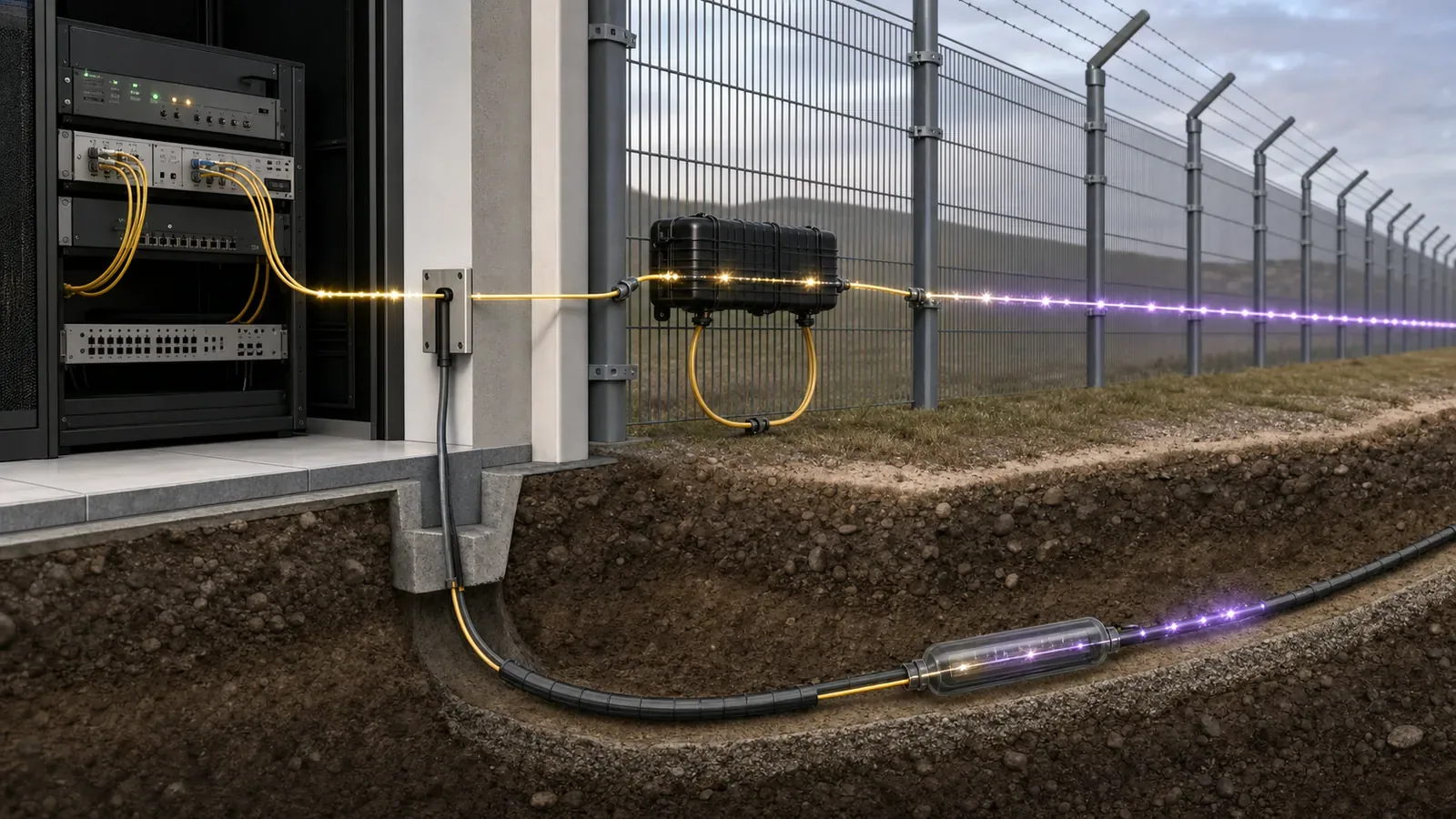
A seven-step framework for evaluating a DAS range claim
1. Start with the Operational Requirement
Define the security problem before examining the product specification. The NPSA Operational Requirement guidance presents a structured process for defining security outcomes before selecting individual measures.
For a DAS project, document:
Required event classes, such as fence cutting, climbing, digging, walking, or vehicle approach.
Required detection area and any excluded sections.
Acceptable localization error for camera or guard dispatch.
Maximum end-to-end alarm latency.
Environmental and operational conditions.
Acceptable unwanted-alarm performance.
Required behavior after a fiber cut, power failure, network loss, or processor fault.
Without those definitions, a range figure cannot be accepted or rejected objectively.
2. Normalize the topology
Request a route drawing that identifies the interrogator, launch fiber, sensing sections, service loops, splices, connectors, gates, crossings, return paths, and termination.
Calculate both total optical length and protected physical length. Confirm whether the claim applies per channel, per interrogator, or across several units. For looped and redundant designs, determine whether the advertised distance describes normal operation, post-fault operation, or the sum of multiple channels.
3. Request the optical evidence
The supplier should disclose the fiber type and maximum permitted end-to-end optical loss for the proposed configuration. Review the OTDR baseline, splice schedule, connector interfaces, bend constraints, and loss margin.
Do not accept a laboratory reel as equivalent to an installed route. A controlled reel may demonstrate optical reach, but it does not reproduce fence coupling, burial conditions, route repairs, mechanical transitions, or environmental noise.
4. Freeze the sensing configuration
Record the interrogator model, software version, pulse and acquisition settings, gauge length, channel spacing, filters, classification model, thresholds, and zone map.
Every range, localization, or detection result must be tied to this configuration. If settings change during a trial, identify which results are affected and repeat those tests. Otherwise, a comparison can combine the strongest result from several incompatible configurations.
5. Demand route-level results
A route-wide average can hide weak sections. Report results by event class, route segment, distance from the interrogator, installation type, and environmental condition.
Present localization as an error distribution, not only a best case or overall average. Detection reporting should expose missed events. Separate sensor faults and unexplained alarms from valid responses to non-threat stimuli such as weather, maintenance, animals, or traffic.
6. Test the complete alarm workflow
The security result includes more than signal acquisition. Measure time from the physical test event to the operator-visible alarm, camera call-up, mapped location, and acknowledgement.
Test integrations using the same VMS, PSIM, SCADA, relay, or network path expected in production. Fast interrogator processing does not compensate for delayed middleware, incorrect camera mapping, or an alarm that lacks sufficient location data for response.
7. Convert the claim into acceptance criteria
The contract should identify the tested configuration, protected route, event classes, test method, required metrics, retest rules, configuration-control process, and remedies for failed sections.
Avoid clauses that accept "up to" performance without defining conditions. The accepted range should be the route that passes the agreed security criteria, not the largest number in the datasheet.
DAS range-claim evidence matrix
For each claim, request evidence specific enough to reproduce or challenge the result:
Maximum fiber length. Request the configuration, optical-loss limit, fiber type, and test trace. Watch for distance stated without optical conditions.
Protected perimeter length. Request a route drawing and the fiber-to-boundary ratio. Watch for lead fiber and loops counted as coverage.
Detection coverage. Request results by event and route segment. Watch for route-wide averages that hide weak sections.
Localization accuracy. Request the error distribution across the route. Watch for spatial resolution substituted for observed accuracy.
Classification performance. Request class-level results and the missed-event record. Watch for generic "AI detection" claims without event-level evidence.
Unwanted-alarm performance. Request a time-normalized log with environmental context. Watch for short demonstrations or undocumented alarm exclusions.
Alarm latency. Request end-to-end timestamps through production integrations. Watch for interrogator processing time presented as total latency.
Cut resilience. Request a fault test and post-cut coverage map. Watch for redundancy claims that omit reduced-mode behavior.
Site field test protocol
A credible proof of concept should be designed before the equipment is tuned.
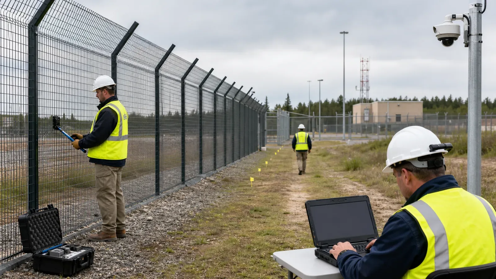
Establish the baseline
Inspect the route, record fence and soil conditions, capture an OTDR trace, map chainage to physical landmarks, and log normal environmental or operational activity.
Create the test matrix
Cross each required event class with representative near, middle, and far route sections; fence types; gates and corners; noisy areas; and relevant weather or operating states. Set the number of trials and confidence method before testing. The project risk owner should approve these values rather than adopting an arbitrary universal threshold.
Separate tuning from acceptance
Use one set of events for installation and calibration. Conduct acceptance trials afterward using frozen settings. Where practical, randomize the event order and keep the operator or classifier unaware of the schedule.
Record every trial
Store the actual event location and time, system-reported location, classification, alarm timestamp, integration output, camera response, and outcome. A miss remains a miss; it should not disappear because a threshold is changed later.
Run a representative background soak
Observe the system during non-threat activity and correlate alarms with wind, rain, traffic, machinery, vegetation, wildlife, maintenance, and unknown causes. A brief staged demonstration cannot establish operational alarm performance.
Test resilience
Verify fiber-cut detection, coverage remaining after a cut, power recovery, network interruption, time synchronization, health monitoring, and configuration restoration.
NPSA functional PIDS evaluations use attack trials to determine Detection Rate and separate false-alarm trials to determine False Alarm Rate. A project acceptance test is not equivalent to NPSA assurance, but the same principle applies: detection and unwanted-alarm performance require separate, structured evidence. See the NPSA PIDS evaluation schemes.
When DAS is the wrong technology
DAS should not be selected solely because it advertises the longest distance. A different architecture may be better when the site has a short, naturally segmented perimeter; cannot provide a stable and maintainable fiber route; needs volumetric detection far from the cable; or has highly heterogeneous sections that cannot share a practical sensing configuration.
DAS may also be a poor fit when the organization cannot support calibration, configuration control, alarm review, and fiber maintenance. The long-perimeter fiber-optic IDS design guide covers the broader architecture and integration questions that should be resolved before procurement.
Where continuous long-range localization fits the Operational Requirement, evaluate a DAS platform such as FortSense Ultra against the evidence framework above. For shorter sites that need physical zones rather than continuous DAS localization, FortSense 4 may provide a simpler zone-based fiber-optic architecture. Radar, microwave, buried sensors, video analytics, or layered technologies may be preferable where the threat and terrain demand capabilities that one sensing cable cannot provide.
The decision must follow the threat model and response workflow, not the largest range number.
Keep the acceptance evidence with the system
Store the accepted configuration, OTDR baseline, chainage map, trial evidence, software versions, alarm rules, and integration mappings with the commissioning package. Repeat affected acceptance tests after cable repair, route modification, major software changes, classifier replacement, or material threshold changes.
For critical sites, connect the range decision to the wider critical infrastructure perimeter-security design. US projects should also account for regional integration and support requirements through the United States perimeter-security overview.
Turn the selected range scenario into field evidence with a controlled fiber PIDS proof-of-concept plan that freezes the tested configuration and separates tuning from blind trials.
If route, coupling, nuisance conditions, response value, or proof cannot support the range case, use the DAS no-fit decision framework before carrying the architecture into procurement.
Bring the perimeter drawing, fiber route, event classes, environmental risks, and monitoring workflow to a FortSense design review. The design review can determine whether DAS, a zone-based controller, or a layered detection architecture fits the project before a datasheet range becomes a procurement commitment.
After usable route coverage is established, normalize competing lifecycle bids with the fiber PIDS cost-per-protected-kilometer TCO model.
Existing unused fiber is only a range candidate. Apply the dark-fiber DAS reuse feasibility gates before treating optical reach as accepted perimeter coverage.
Technical sources
IEC 61757-3-2:2022 - distributed fiber-optic acoustic sensing terminology, performance parameters, and interrogator test methods.
NPSA Operational Requirements guidance - structured definition of security outcomes and requirements.
NPSA PIDS evaluation schemes - separate Detection Rate and False Alarm Rate trial methodology.
Recent Progress in Phase-Sensitive OTDR Performance Enhancement - sensing range, spatial resolution, sensitivity, and SNR tradeoffs.
Research Progress in Distributed Acoustic Sensing Techniques - DAS operating principles and performance-enhancement approaches.
Variable Gauge Length: Processing Theory and Applications - gauge-length effects on SNR and signal distortion.
Real-world DAS perimeter classification study - installation-dependent fence-mounted and buried classification results.
Range and localization are separate acceptance dimensions. Use the fiber PIDS localization accuracy claims guide to normalize chainage mapping, error percentiles, wrong-segment results, and camera-cueing tests.
For border corridors, apply the same range-claim discipline to the full route design in border-security DAS perimeter detection design.