Fiber PIDS localization accuracy is the measured difference between a known physical event position and the location reported by the installed system. Channel spacing, gauge length, spatial resolution, and a vendor’s best observed result are not substitutes for that installed measurement.
Compare suppliers only after they use the same event definitions, route reference, ground-truth method, frozen configuration, reporting statistics, and acceptance conditions. Evaluate optical reach separately with the DAS detection-range claims guide.
For broader architecture and vendor screening, start with the fiber-optic fence sensor buyer guide. This page owns the narrower due-diligence question: whether two localization claims are genuinely comparable.
Localization accuracy is not spatial resolution
IEC 61757-3-2:2022 specifies terminology, characteristic performance parameters, and test or calculation methods for phase-sensitive coherent OTDR interrogation units. Its scope helps compare instrument characteristics; it does not certify the localization accuracy of a completed perimeter installation.
Localization accuracy: difference between ground-truth event position and the system-reported position. It does not establish probability of detection or classification accuracy.
Spatial resolution: minimum spatial separation at which distinct disturbances can be resolved under stated conditions. It does not establish absolute map accuracy.
Channel spacing: distance between adjacent output samples or virtual channels. Dense samples may overlap and are not necessarily independent.
Gauge length: fiber interval over which a DAS measurement is formed. It affects signal response but is not automatically the alarm location error.
Chainage: distance measured along the protected physical route. It must be mapped to optical distance and, where required, GIS coordinates.
Event-separation capability: ability to report nearby simultaneous events separately. It does not establish the accuracy of either reported position.
Peer-reviewed DAS literature distinguishes spatial resolution from gauge length and shows why gauge length, sampling interval, and localization must be reported separately. See the review of distributed fiber acoustic sensing with phase-sensitive OTDR.
Decision rule: reject a localization number defined only by channel spacing, readout interval, gauge length, or spatial resolution.
Why identical-looking accuracy claims may not be comparable
A statement such as “plus or minus five meters” is incomplete until the supplier defines the statistic and the test population. It may describe a maximum, a standard deviation, a design tolerance, an average, or one favorable trial.
Does the number include every valid alarm or only alarms that produced a location?
Is error measured along optical distance, physical chainage, route segment, or map coordinates?
Were tests performed on a laboratory spool, a demonstration fence, or the installed route?
Which event classes, fence types, burial conditions, and environmental states were included?
Were near, middle, and far route sections tested?
Were gates, corners, splices, service loops, repairs, and parallel segments included?
Were outliers, wrong-segment alarms, and failed localizations retained?
Was the production map, VMS, camera cue, and operator display part of the test?
Normalized measurement: absolute localization error equals the absolute value of reported chainage minus ground-truth chainage. If the system reports coordinates, also verify that the correct physical perimeter segment was selected.
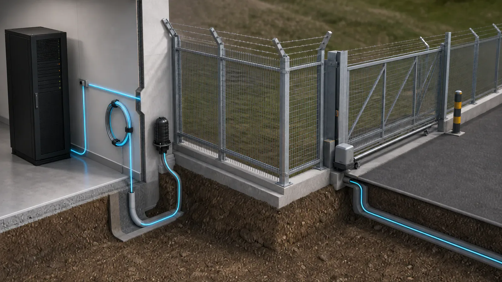
Chainage calibration connects optical distance to the perimeter
A DAS interrogator estimates position from the optical travel time of backscattered light. Optical distance is not automatically the same as protected route distance. Lead-in fiber, slack, service loops, gate transitions, repair coils, detours, and redundant paths can all separate optical position from fence or buried-route chainage.
The Energistics PRODML DAS calibration model explicitly distinguishes optical path distance from facility length and supports multiple calibration points. A published fiber-optic pipeline surveillance study likewise calibrated fiber distance to physical asset position because the cable path and stored loops did not perfectly follow the monitored route.
Build a controlled chainage table containing:
Interrogator channel or optical position.
Physical fence or buried-route chainage.
Surveyed or otherwise controlled map position and its uncertainty.
Fence section, burial condition, gate, corner, splice, transition, and service-loop identifiers.
Camera coverage, PTZ preset, security zone, and operator response instruction.
Configuration version and date of the approved mapping.
Known-location mechanical tests can associate DAS response with landmarks, but one tap is not perfect ground truth. Research on near-source effects in DAS tap tests shows that cable geometry, gauge-length averaging, and local response can complicate interpretation. Use multiple reference points and keep separate points for validation.
Eight questions that normalize a localization claim
Metric definition. Request the written calculation. Treat “precision,” “resolution,” and “accuracy” used interchangeably as a warning.
Reported coordinate. Require optical distance, physical chainage, segment ID, or map-coordinate definitions and conversion rules.
Ground truth. Require the controlled marker or survey method, route drawing, and uncertainty. An undocumented installer estimate is insufficient.
Event population. Require event class, execution method, repetitions, and inclusion rules. One strong impact cannot represent every threat.
Frozen configuration. Record interrogator, firmware, software, gauge length, channel spacing, filters, thresholds, classifier version, and mapping files.
Route coverage. Require near, middle, far, and difficult sections instead of the supplier’s best segment.
Statistical report. Require trial-level results, percentiles, maximum error, wrong-segment rate, and localization yield instead of one average.
Operational integration. Verify the production VMS map, selected camera, PTZ preset, operator display, and dispatch location, not only the sensor console.
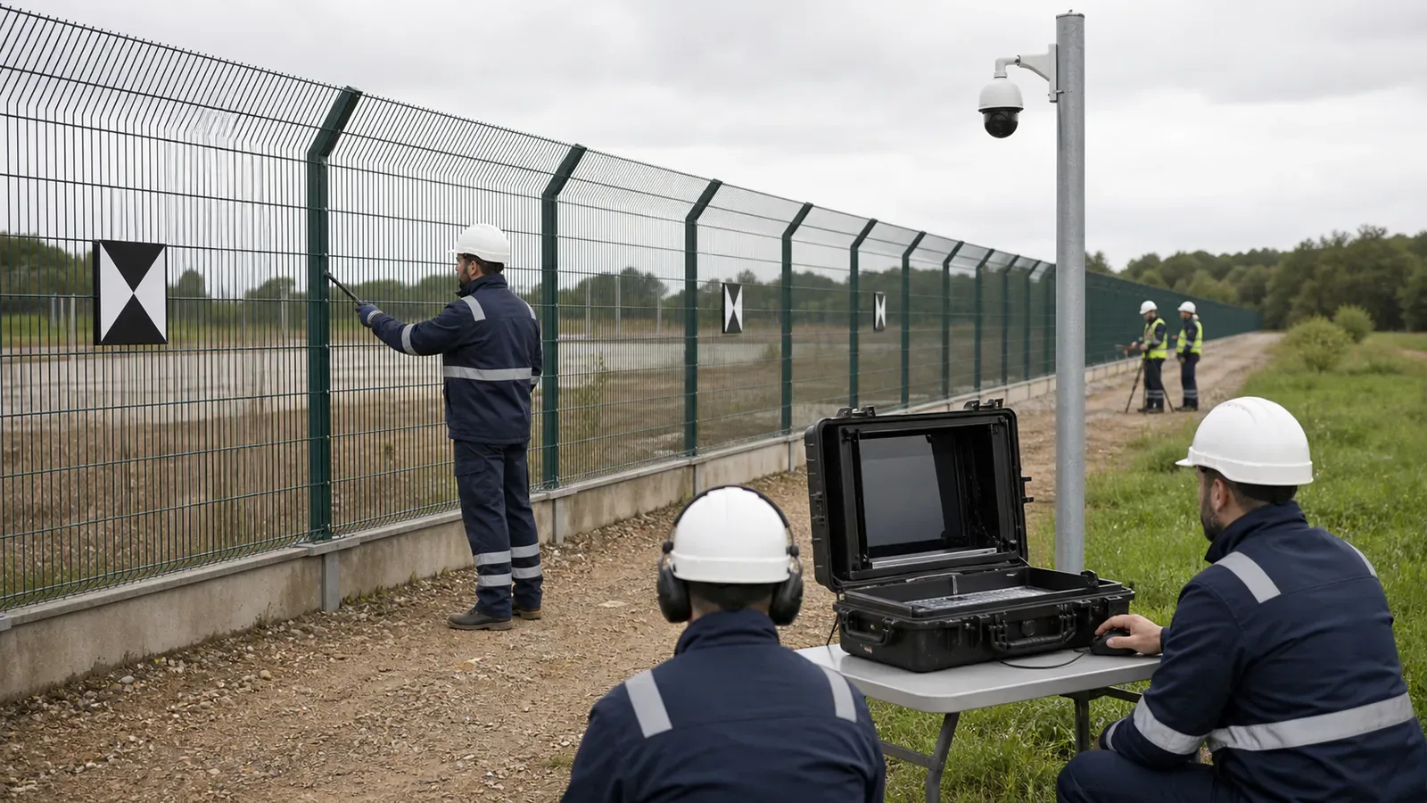
Run a route-stratified blind localization field test
The method below is an engineering evaluation framework, not a universal IEC or NPSA procedure. The project risk owner must define the required event classes, sample size, acceptance values, and confidence.
1. Freeze the tested configuration
Record the complete hardware, firmware, processing, mapping, threshold, filter, and integration configuration. Results remain attributable only to that frozen version.
2. Establish independent ground truth
Distribute controlled points across near, middle, and far sections; straight runs; corners; gates; cable transitions; splices; repair loops; route detours; different fence or burial conditions; and parallel sections where the wrong segment could be selected. Hold back validation points that were not used to build the mapping.
3. Define repeatable event methods
Use the project’s threat events, such as cutting, climbing, lifting, digging, walking, or vehicle approach. Record the method closely enough to repeat it, and report results by event class because different events disturb different lengths of fence, soil, and cable.
4. Separate calibration from acceptance
Complete mapping and tuning first. Freeze the configuration, then conduct acceptance trials. Where practical, randomize location and event order, and keep the person reviewing the alarm output unaware of the expected position.
5. Preserve every valid trial
Record ground-truth chainage and segment, event class and time, reported chainage and map position, signed and absolute error, whether a location was produced, whether the correct camera scene appeared, configuration version, and environmental context. Do not delete outliers after tuning; document the change and retest the affected population.
6. Report the full error distribution
Signed error to expose systematic offset.
Median absolute error to describe typical performance.
An agreed upper percentile such as P90 or P95, selected by the project rather than assumed universally.
Maximum observed error and the conditions associated with it.
Localization yield meaning the share of detected alarms that produced a valid location.
Wrong-segment rate especially where fence runs are close together.
Results by event class and route section so a good aggregate cannot hide a weak condition.
Percentiles prevent a favorable average from hiding an operationally important tail. No universal percentile or distance threshold is correct for every perimeter.
7. Test the operator outcome
Run the alarm through the production VMS, PSIM, map, camera, and control-room workflow. NPSA perimeter intrusion detection guidance recommends varied, repeated commissioning attacks and testing integrated PIDS and video verification as a complete system, with retesting after adjustments.
Localization accuracy must support camera verification
The required accuracy comes from the response workflow, not a datasheet. A small chainage error can cue the wrong camera where two fence sections run close together. A larger error may remain usable on a straight, unobstructed section covered by a wide fixed-camera view.
Verify that every tested alarm:
Selects the correct physical segment.
Opens the intended camera or PTZ preset.
Places the event inside a usable verification view.
Gives the operator an unambiguous location description.
Preserves enough event and map information for dispatch and investigation.
ONVIF Profile M supports analytics metadata, events, and geolocation metadata. It can help exchange event information, but it does not automatically create a correct chainage-to-camera mapping. The integration still needs project-specific configuration and testing.
See how to verify perimeter alarms with cameras for the broader video workflow and fiber optic versus fence sensor comparison for the sensing architecture.
Write localization acceptance into the contract
Avoid a clause that states only “localization accuracy: plus or minus X meters.” Define the event classes, installed route sections, environmental conditions, frozen production configuration, ground-truth method, statistic, location yield, wrong-segment handling, and integrated camera outcome.
Acceptance-clause structure: For the defined event classes and route sections, the installed system shall report the correct perimeter segment and meet the project’s agreed median, upper-percentile, maximum-error, and localization-yield limits. Independent validation points shall cover representative and difficult sections. The production map and camera-verification workflow shall be included. Configuration changes that can affect localization require documented impact review and retesting.
The project team must fill in the values from its Operational Requirement, camera geometry, response procedure, and consequences of sending personnel to the wrong location.
Choose continuous localization or physical zones
Continuous DAS localization fits long perimeters, corridors, pipelines, borders, and distributed assets where operators need chainage-level positioning. Evaluate FortSense Ultra for this architecture and the separate guide to fiber-optic intrusion detection for long perimeters.
A physically zoned architecture can be simpler when the response procedure and cameras already follow fixed sectors, or when continuous chainage adds little operational value. Evaluate FortSense 4 for zone-based detection and integration.
For high-consequence deployments, connect the acceptance method to the critical infrastructure security design and applicable deployment requirements, including the United States perimeter security program context where relevant. The better architecture is the one that produces a location the response workflow can use.
Implementation note
Store the approved chainage table, GIS layer, ground-truth records, raw trial results, configuration versions, camera mappings, and acceptance report with the commissioning package. Revalidate affected sections after cable repair, service-loop changes, route alterations, interrogator replacement, processing changes, GIS remapping, or camera-preset changes.
Compare localization against the real response workflow
Place localization scoring inside a frozen, blind fiber PIDS proof-of-concept protocol so surveyed ground truth, configuration state, route conditions, and retesting remain traceable.
Bring the route drawing, fiber topology, event classes, camera plan, and response procedure to a FortSense perimeter design review. FortSense can help determine whether continuous DAS localization, physical-zone detection, or a layered architecture fits the site.
Keep localization-error trials separate from the broader blind PIDS intrusion testing protocol, which evaluates detection, alarm presentation, camera verification, and operator action.
After localization error is measured, apply its error envelope through the geospatial alarm-to-camera mapping model instead of selecting a camera from the reported point alone.
For border corridors, test localization accuracy against camera views and patrol access using the border-security DAS design guide.